10 Channel Output Module
The 10 channel Output Module is a GOcontroll Moduline compatible expansion card to add 10 high side output ports to your modular controller. The outputs are protected and configurable individually for a wide range of applications. The configuration can easily be set by the user in Node-RED.
Applications
- High side switching of multiple low-power actuators (up to 10 outputs)
- Driving solenoid valves (pneumatic or hydraulic) on-off
- Energising relay and contactor coils
- Controlling indicator lamps, beacons and status lights
- Actuating small solenoids and electromagnets
- Duty-cycle (PWM) controlled outputs (0-100%) for tasks such as lamp dimming
Features
- 10 high side outputs, each independently configurable
- Each output can be switched on-off or duty-cycle controlled (0-100%)
- Selectable PWM frequency per channel pair
- Module diagnostics (temperature, supply voltage and total module current) reported to the controller
- Each output is short circuit and over temperature protected.
- Module supply is reverse polarity protected
- Module power supply is load dump protected (ISO 7637)
- Bad ground connection detection (earth loop protection)
- External supply voltage range from 8 to 32 Volt
Technical Specifications
The technical specifications are listed in the table below.
| Min | Nom | Max | Unit | |
|---|---|---|---|---|
| Supply rail voltage (normal operation) | 8 | 32 | Volt | |
| Nominal load current for each channel* | 1 | A | ||
| Peak load current for each channel* | 1.8 | A | ||
| PWM control frequency | 200 | 1000 | Hz |
Connectors may never be hot-plugged. Remove power before removing or installing connectors.
Connect all supply and ground pins before driving an actuator; otherwise the processor board and module can be permanently damaged.
If a safety relay removes the module power, only interrupt the positive supply (+) — never the ground.
Pinout Moduline L4
The eight module expansion slots are directed to four connectors in front of the controller. Connector A,B,D and E. If a module is plugged into a specific expansion slot, one half of the corresponding connector is used to interface this module. The picture below gives an overview of the connectors with their related module expansion slots.
The pictures below show the connector pinning of the 10 Channel Output module. Be aware of the different pinouts when the module is plugged into even or odd module slots.
Module on even slot
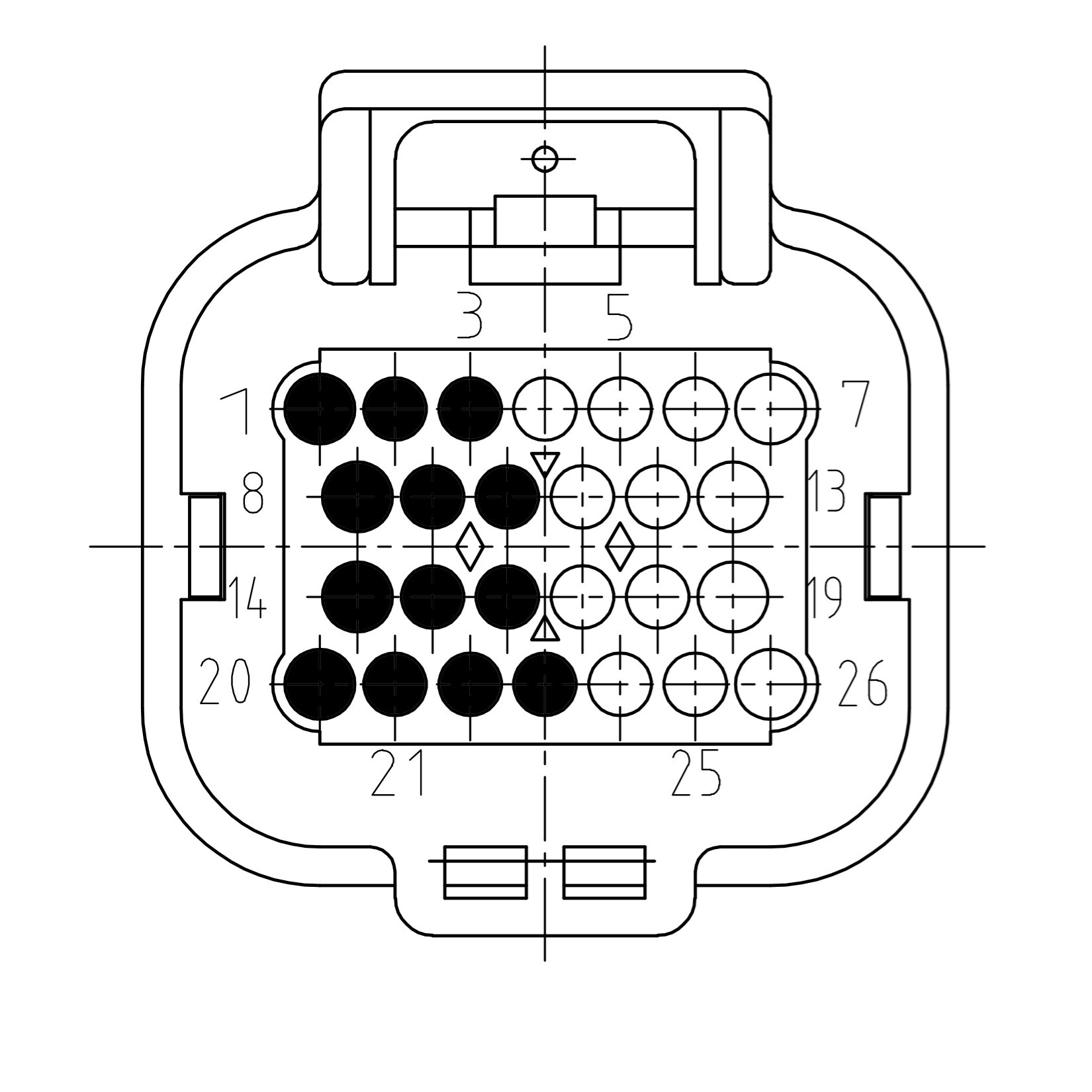
| Pin | Function | Description |
|---|---|---|
| 1 | SUPPLY | Module supply |
| 2 | SUPPLY | Module supply |
| 3 | OUT9 | Signal out 9 |
| 8 | OUT1 | Signal out 1 |
| 9 | OUT3 | Signal out 3 |
| 10 | OUT5 | Signal out 5 |
| 14 | OUT2 | Signal out 2 |
| 15 | OUT4 | Signal out 4 |
| 16 | OUT6 | Signal out 6 |
| 20 | GROUND | Module ground |
| 21 | OUT7 | Signal out 7 |
| 22 | OUT8 | Signal out 8 |
| 23 | OUT10 | Signal out 10 |
Module on uneven slot
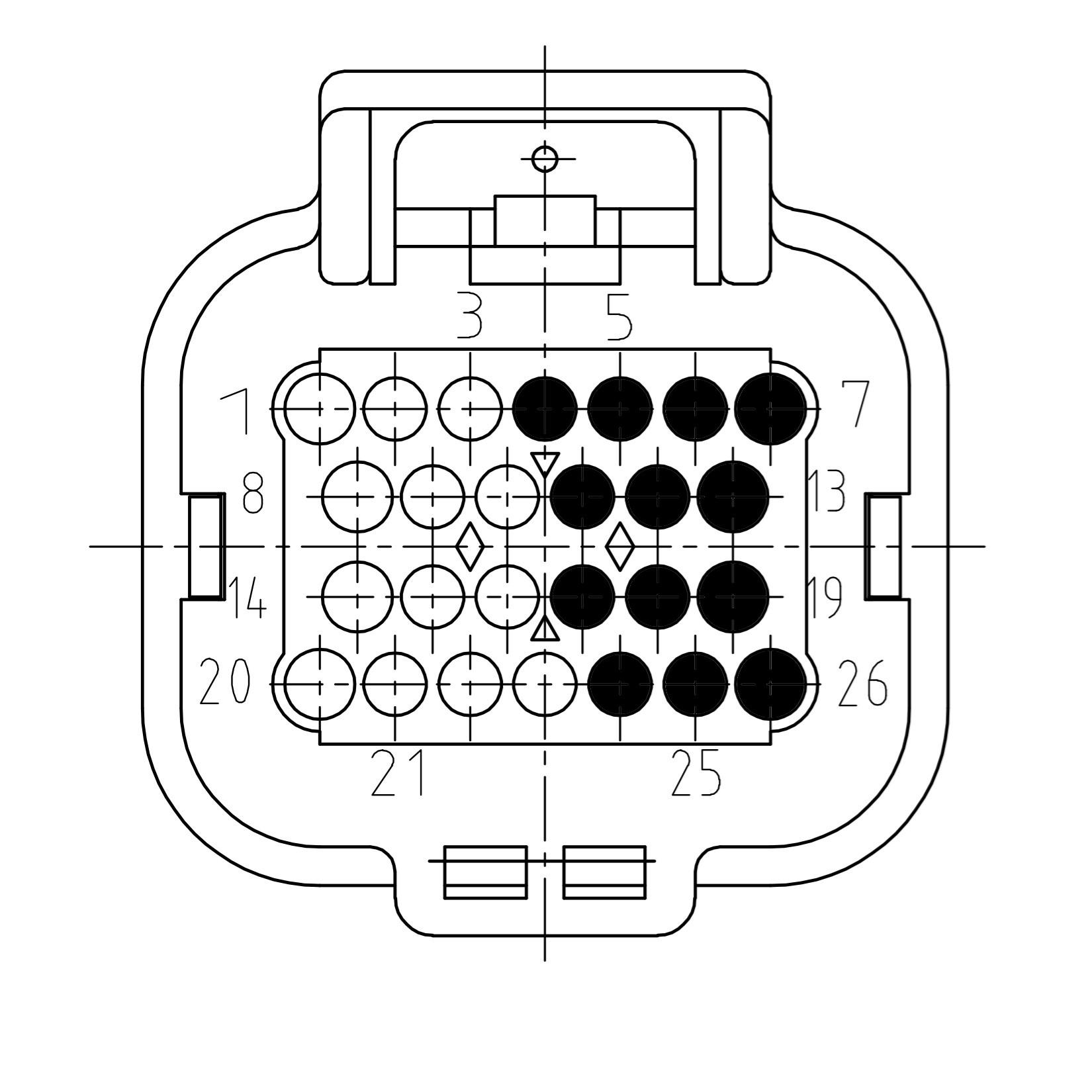
| Pin | Function | Description |
|---|---|---|
| 4 | OUT10 | Signal out 10 |
| 5 | OUT9 | Signal out 9 |
| 6 | SUPPLY | Module supply |
| 7 | SUPPLY | Module supply |
| 11 | OUT5 | Signal out 5 |
| 12 | OUT3 | Signal out 3 |
| 13 | OUT1 | Signal out 1 |
| 17 | OUT6 | Signal out 6 |
| 18 | OUT4 | Signal out 4 |
| 19 | OUT2 | Signal out 2 |
| 24 | OUT8 | Signal out 8 |
| 25 | OUT7 | Signal out 7 |
| 26 | GROUND | Module ground |
Pinout Moduline M1
The four module expansion slots are directed to the two main connectors of the controller. Connector A and B. If a module is plugged into a specific expansion slot, one half of the corresponding connector is used to interface this module. The picture below gives an overview of the connectors with their related module expansion slots.
The pictures below show the connector pinning of the 10 Channel Output module. Be aware of the different pinouts when the module is plugged into even or odd module slots.
Module on even slot
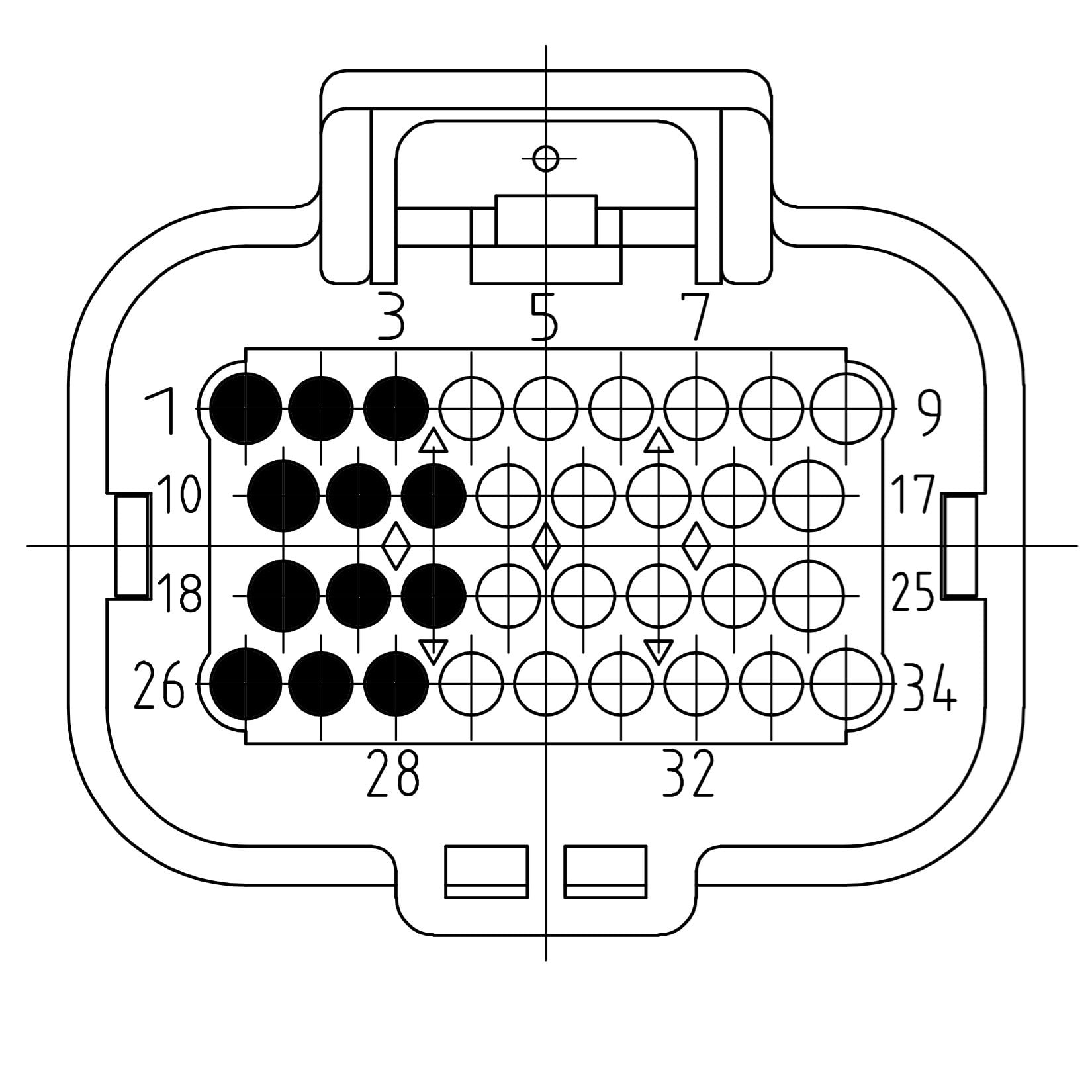
| Pin | Function | Description |
|---|---|---|
| 1 | SUPPLY | Module supply |
| 2 | SUPPLY | Module supply |
| 3 | OUT9 | Signal out 9 |
| 10 | OUT1 | Signal out 1 |
| 11 | OUT3 | Signal out 3 |
| 12 | OUT5 | Signal out 5 |
| 18 | OUT2 | Signal out 2 |
| 19 | OUT4 | Signal out 4 |
| 20 | OUT6 | Signal out 6 |
| 26 | GROUND | Module ground |
| 27 | OUT7 | Signal out 7 |
| 28 | OUT8 | Signal out 8 |
| 29 | OUT10 | Signal out 10 |
Module on uneven slot
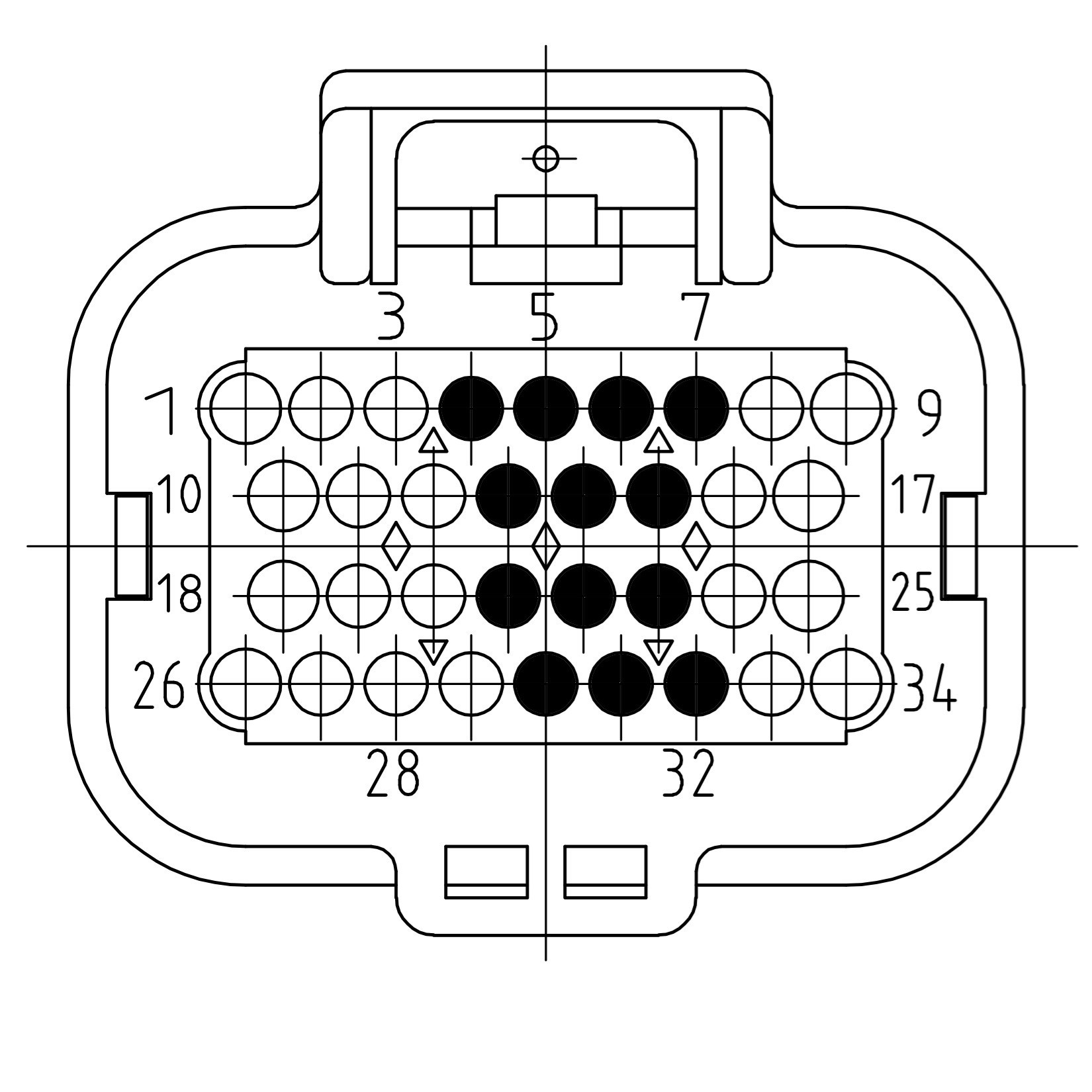
| Pin | Function | Description |
|---|---|---|
| 4 | OUT10 | Signal out 10 |
| 5 | OUT9 | Signal out 9 |
| 6 | SUPPLY | Module supply |
| 7 | SUPPLY | Module supply |
| 13 | OUT5 | Signal out 5 |
| 14 | OUT3 | Signal out 3 |
| 15 | OUT1 | Signal out 1 |
| 21 | OUT6 | Signal out 6 |
| 22 | OUT4 | Signal out 4 |
| 23 | OUT2 | Signal out 2 |
| 30 | OUT8 | Signal out 8 |
| 31 | OUT7 | Signal out 7 |
| 32 | GROUND | Module ground |
Pinout Moduline S1
The two module expansion slots are directed to a single connector on the controller. If a module is plugged into a specific expansion slot, one half of the connector is used to interface this module. The picture below gives an overview of the connector with its related module expansion slots.
The pictures below show the connector pinning of the 10 Channel Output module. Be aware of the different pinouts when the module is plugged into the even or the odd module slot.
Module on even slot
| Pin | Function | Description |
|---|---|---|
| 1 | SUPPLY | Module supply |
| 2 | SUPPLY | Module supply |
| 3 | OUT9 | Signal out 9 |
| 10 | OUT1 | Signal out 1 |
| 11 | OUT3 | Signal out 3 |
| 12 | OUT5 | Signal out 5 |
| 18 | OUT2 | Signal out 2 |
| 19 | OUT4 | Signal out 4 |
| 20 | OUT6 | Signal out 6 |
| 26 | GROUND | Module ground |
| 27 | OUT7 | Signal out 7 |
| 28 | OUT8 | Signal out 8 |
| 29 | OUT10 | Signal out 10 |
Module on uneven slot
| Pin | Function | Description |
|---|---|---|
| 4 | OUT10 | Signal out 10 |
| 5 | OUT9 | Signal out 9 |
| 6 | SUPPLY | Module supply |
| 7 | SUPPLY | Module supply |
| 13 | OUT5 | Signal out 5 |
| 14 | OUT3 | Signal out 3 |
| 15 | OUT1 | Signal out 1 |
| 21 | OUT6 | Signal out 6 |
| 22 | OUT4 | Signal out 4 |
| 23 | OUT2 | Signal out 2 |
| 30 | OUT8 | Signal out 8 |
| 31 | OUT7 | Signal out 7 |
| 32 | GROUND | Module ground |
Pinout Moduline HMI1
The two module expansion slots are directed to a single connector on the controller. If a module is plugged into a specific expansion slot, one half of the connector is used to interface this module. The picture below gives an overview of the connector with its related module expansion slots.
The pictures below show the connector pinning of the 10 Channel Output module. Be aware of the different pinouts when the module is plugged into the even or the odd module slot.
Module on even slot
| Pin | Function | Description |
|---|---|---|
| 1 | SUPPLY | Module supply |
| 2 | SUPPLY | Module supply |
| 3 | OUT9 | Signal out 9 |
| 10 | OUT1 | Signal out 1 |
| 11 | OUT3 | Signal out 3 |
| 12 | OUT5 | Signal out 5 |
| 18 | OUT2 | Signal out 2 |
| 19 | OUT4 | Signal out 4 |
| 20 | OUT6 | Signal out 6 |
| 26 | GROUND | Module ground |
| 27 | OUT7 | Signal out 7 |
| 28 | OUT8 | Signal out 8 |
| 29 | OUT10 | Signal out 10 |
Module on uneven slot
| Pin | Function | Description |
|---|---|---|
| 4 | OUT10 | Signal out 10 |
| 5 | OUT9 | Signal out 9 |
| 6 | SUPPLY | Module supply |
| 7 | SUPPLY | Module supply |
| 13 | OUT5 | Signal out 5 |
| 14 | OUT3 | Signal out 3 |
| 15 | OUT1 | Signal out 1 |
| 21 | OUT6 | Signal out 6 |
| 22 | OUT4 | Signal out 4 |
| 23 | OUT2 | Signal out 2 |
| 30 | OUT8 | Signal out 8 |
| 31 | OUT7 | Signal out 7 |
| 32 | GROUND | Module ground |