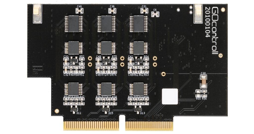
The 6 Channel Input Module is a GOcontroll Moduline-compatible expansion card that adds six high-performance, general-purpose input channels to your modular control system. Each input can be individually configured to read analog voltages, digital states, frequency signals (up to 10 kHz), duty cycles, encoder pulses, or rotational speed.
To maximize flexibility, each channel supports configurable input voltage ranges, software-selectable pull-up and pull-down resistors, and optional low-pass filtering to stabilize noisy signals. The module also features three dedicated 5V sensor supply outputs, making it ideal for directly powering and interfacing with external sensors.

Applications
Features
Technical specifications
The technical specifications are listed in the table below.
| Measuring range | Min | Nom | Max | Unit | |
|---|---|---|---|---|---|
| Input voltage range (analog and digital) | 0 | 24 | Volt | ||
| Analog input sample resolution | 0 – 5 Volt | 12 | Bit | ||
| 0 – 12 Volt | 12 | Bit | |||
| 0 – 24 Volt | 12 | Bit | |||
| Analog input sample frequency | 1 | 10 | kHz | ||
| Analog filter samples | 1 | 1000 | Samples | ||
| Digital input low voltage | 0 – 5 Volt | 1,5 | Volt | ||
| 0 – 12 Volt | 3,6 | Volt | |||
| 0 – 24 Volt | 7,2 | Volt | |||
| Digtal input high voltage | 0 – 5 Volt | 3,0 | Volt | ||
| 0 – 12 Volt | 7,2 | Volt | |||
| 0 – 24 Volt | 14,4 | Volt | |||
| Input impedance (configuration dependent) | 0 – 5 Volt | 31,5k | Ohm | ||
| 0 – 12 Volt | 14,5k | Ohm | |||
| 0 – 24 Volt | 12,1k | Ohm | |||
| Pull up values | 3,2k | Ohm | |||
| 4,7k | Ohm | ||||
| 10k | Ohm | ||||
| Pull down values | 3,2k | Ohm | |||
| 4,7k | Ohm | ||||
| 10k | Ohm | ||||
| 5 volt sensor supply current (for each supply pin) | 40 | 45 | mA | ||
| Module weight | 13 | gram |
Pinout Moduline II, III & IV
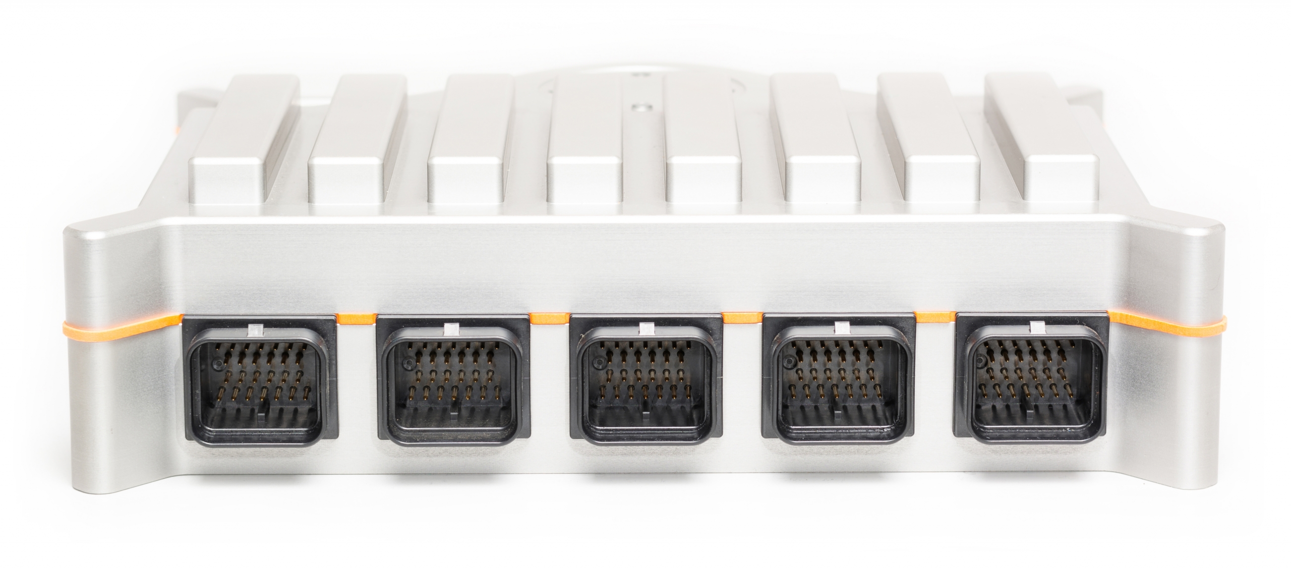
The eight module expansion slots are directed to four connectors in front of the controller. Connector A,B,D and E. If a module is plugged into a specific expansion slot, one half of the corresponding connector is used to interface this module. The picture below gives an overview of the connectors with their related module expansion slots.
Connector C ( in the middle) is used for controller supply and some optional CAN bus connections.
Connector A
Module 1 & 2
Module 3 & 4
System connections
Module 5 & 6
Module 7 & 8
Connector B
Connector C
Connector E
Connector D
The picture below shows the connector pinning from the Input Module. Be aware of the different pinouts when the module is plugged into even or odd module slots.
Module on even slot

| Pin | Function | Description |
|---|---|---|
| 1 | SUPPLY | 5V sensor supply |
| 2 | SUPPLY | 5V sensor supply |
| 3 | SUPPLY | 5V sensor supply |
| 8 | IN1 | Signal in 1 |
| 9 | IN3 | Signal in 3 |
| 10 | IN5 | Signal in 5 |
| 14 | IN2 | Signal in 2 |
| 15 | IN4 | Signal in 4 |
| 16 | IN6 | Signal in 6 |
| 20 | GROUND | Sensor ground |
| 21 | GROUND | Sensor ground |
| 22 | GROUND | Sensor ground |
Module on uneven slot

| Pin | Function | Description |
|---|---|---|
| 7 | SUPPLY | 5V sensor supply |
| 6 | SUPPLY | 5V sensor supply |
| 5 | SUPPLY | 5V sensor supply |
| 13 | IN1 | Signal in 1 |
| 12 | IN3 | Signal in 3 |
| 11 | IN5 | Signal in 5 |
| 19 | IN2 | Signal in 2 |
| 18 | IN4 | Signal in 4 |
| 17 | IN6 | Signal in 6 |
| 26 | GROUND | Sensor ground |
| 25 | GROUND | Sensor ground |
| 24 | GROUND | Sensor ground |
Pinout Moduline Mini I
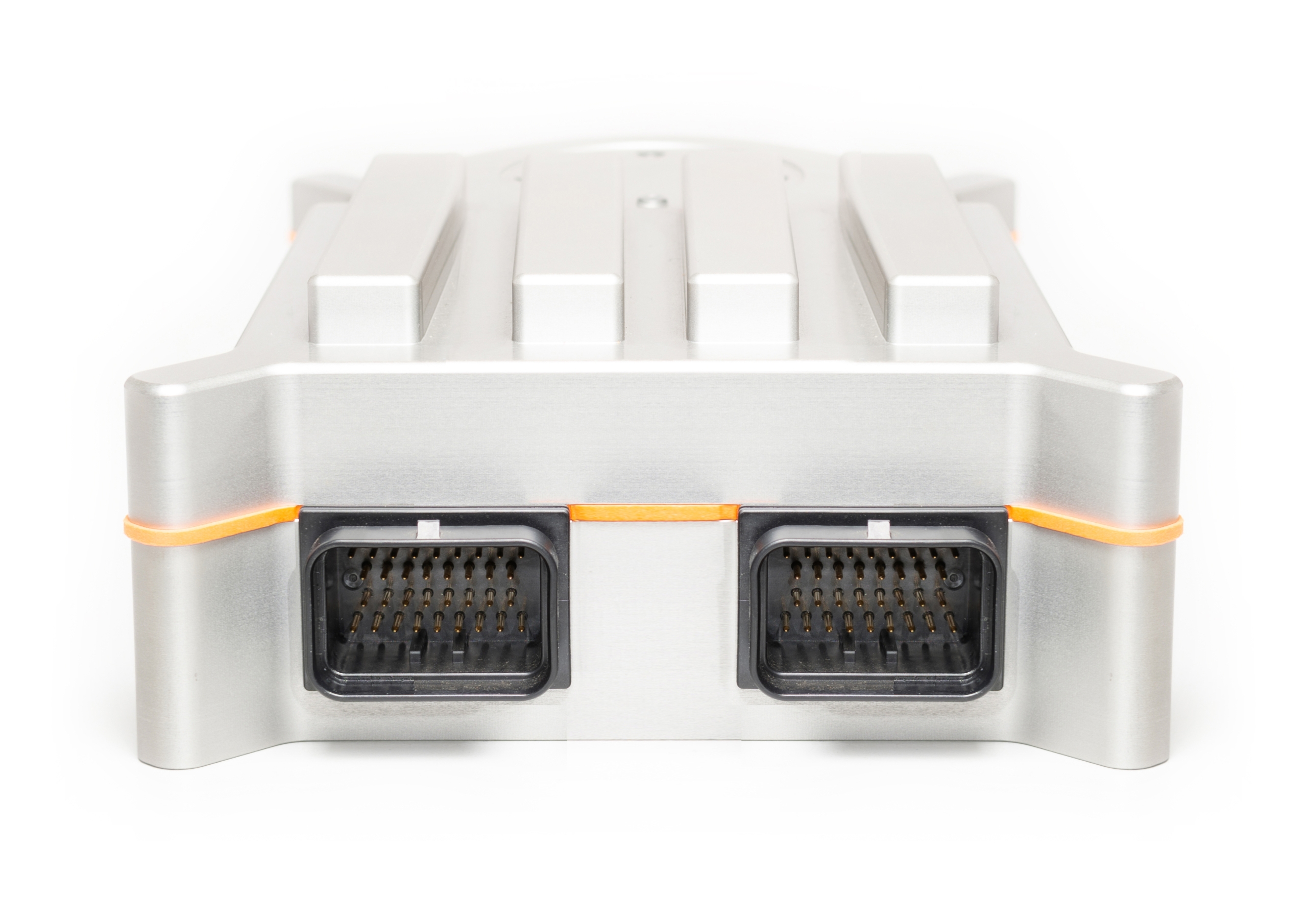
The four module expansion slots are directed to the two main connectors of the controller. Connector A and B. If a module is plugged into a specific expansion slot, one half of the corresponding connector is used to interface this module. The picture below gives an overview of the connectors with their related module expansion slots.
Connector B ( on the left in this view) is also used for controller supply, a controller enable- and reset-input and a CAN bus interface. Connector A also offers a CAN bus interface and on top of that two controller enable inputs.
Module 2 & 1
Module 4 & 3
Connector A
Connector B
The picture below shows the connector pinning from the Input Module. Be aware of the different pinouts when the module is plugged into even or odd module slots.
Module on even slot

| Pin | Function | Description |
|---|---|---|
| 1 | SUPPLY | 5V sensor supply |
| 2 | SUPPLY | 5V sensor supply |
| 3 | SUPPLY | 5V sensor supply |
| 10 | IN1 | Signal in 1 |
| 11 | IN3 | Signal in 3 |
| 12 | IN5 | Signal in 5 |
| 18 | IN2 | Signal in 2 |
| 19 | IN4 | Signal in 4 |
| 20 | IN6 | Signal in 6 |
| 26 | GROUND | Sensor ground |
| 27 | GROUND | Sensor ground |
| 28 | GROUND | Sensor ground |
Module on uneven slot

| Pin | Function | Description |
|---|---|---|
| 7 | SUPPLY | 5V sensor supply |
| 6 | SUPPLY | 5V sensor supply |
| 5 | SUPPLY | 5V sensor supply |
| 15 | IN1 | Signal in 1 |
| 14 | IN3 | Signal in 3 |
| 13 | IN5 | Signal in 5 |
| 23 | IN2 | Signal in 2 |
| 22 | IN4 | Signal in 4 |
| 21 | IN6 | Signal in 6 |
| 32 | GROUND | Sensor ground |
| 31 | GROUND | Sensor ground |
| 30 | GROUND | Sensor ground |