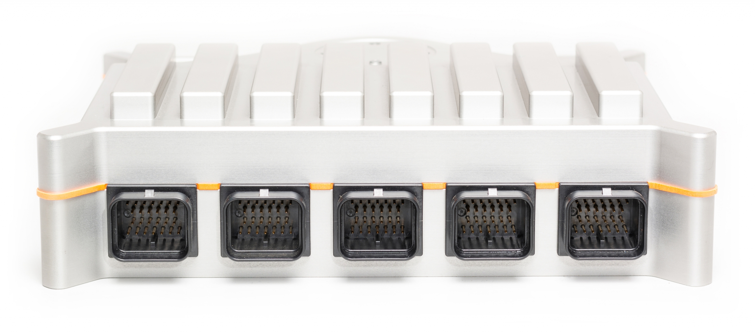
GOcontroll Moduline IV.
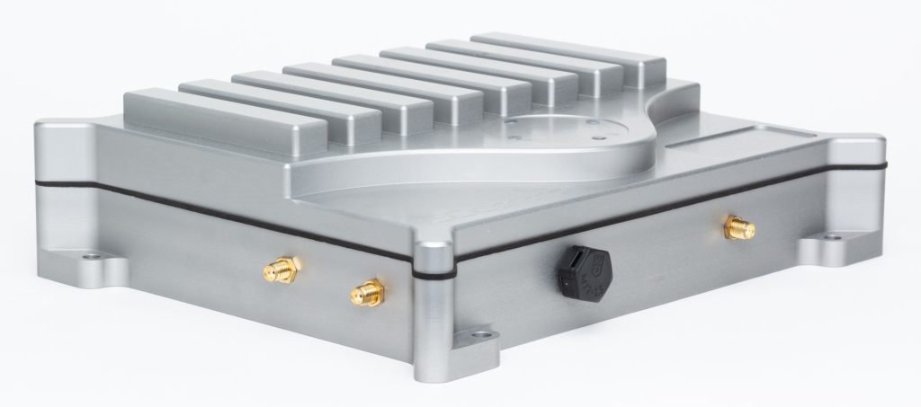
The Moduline IV is our flagship modular embedded controller offering up to 8 IO modules and various communication interfaces. The controller is powered by a powerful application processor from NXP, offering high performance processing and a broad spectrum of peripheral interfaces. The robust enclosure offers IP67 protection and is equipped with a pressure equilibrium/vent plug to reduce the risk of condensation buildup from moisture in the air. It also protects the electronics inside from impacts and other influences the harsh environment of automotive applications may provide. The enclosure is CNC milled from billet EN-AW5083 Aluminum and anodized grey.
The Moduline family runs on Linux which allows various software options such as MATLAB/Simulink and Node-RED. These software tools utilize visual programming which significantly speeds up algorithm development.
The flexible hardware design of the Moduline family allows for complex and/or unusual controller configurations. The hardware itself is designed to withstand the harsch conditions of automotive applications and has been tested according to ECE-R10 by Kiwa Dare.
If you have a GOcontroll Moduline IV controller, the wiki environment will help to setup the controller.

Onboard features.
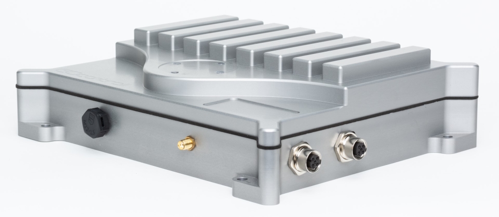
The GOcontroll Moduline IV controller is standard equipped with some features which can be used in applications without the need of extra modules plugged into the controller.
| Feature | Specification |
|---|---|
| 8 Module slots | For Moduline compatible modules |
| 4 Built in programmable LEDs | High brightness multicolor RGB |
| USB | 2.0 |
| Ethernet | 10/100 Mbps |
| 4 x CAN | CAN 2.0 B |
| 1 x LIN | Master or slave configuration |
| Bluetooth* | 5.1 BR/EDR/LE, 3MPHY |
| WiFi* | Wi-Fi 4, 802.11 b/g/n |
| Cellular communication* | LTE CAT-4 (LTE-TDD/LTE-FDD/HSPA+/GSM/GPRS/EDGE) |
| Positioning GNSS* | GPS/GLONASS/BeiDou/Galileo |
| Serial communication | RS232 (assembly option) |
* These features are optional and consist of feature-specific hardware modules
Processor specifications.
The GOcontroll Moduline IV controller is equipped with an i.MX8 application processor which is only used for the application. Low level signal processing is handled locally by the modules.

| Moduline IV | Quad Core |
|---|---|
| Processor | i.MX8M |
| Architecture | Quad ARM® Cortex® A53 |
| Flash memory | 4 GB eMMC |
| RAM memory | 1 GB |
| Core speed (for each core available) | 1.6 GHz |
| Boot time for running compiled Simulink models | 3 to 3.5 seconds |
| Boot time for running Node-RED service | 8 to 10 seconds |
Controller connections.
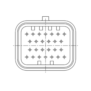
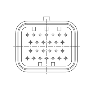
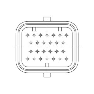
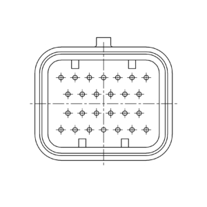
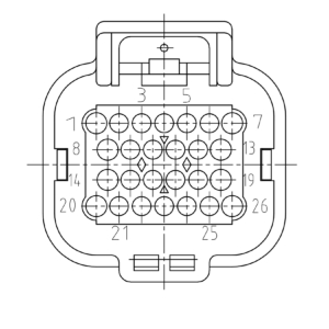
The Moduline IV controller is equipped with five 26 position automotive IO connectors, two M12 connectors and three SMA connectors.
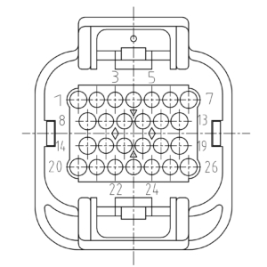
The five automotive IO connectors provide not only up to 80 IO’s, but also 4 CAN bus interfaces, a LIN bus interface, the power supply, a reset input and three enable inputs. These enable inputs will boot the controller when they are high. If a low activate input is detected in software, user can finish some routines/controls before shutting down the controller. The enable pins are only for activation of the controller. The supply for the controller comes from the K30 connection.
Note: The current Moduline IV controllers use 5 identical 26 position automotive IO connectors. These connectors are all A coded. Controllers ordered after Q1 2024 will have the connector configuration listed below.
| E | D | C | B | A |
|---|---|---|---|---|
 |
 |
 |
 |
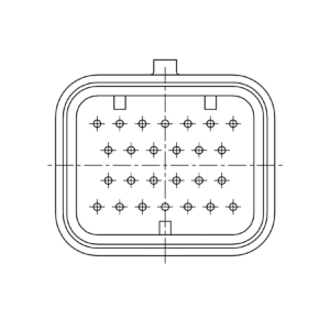 |
| 6473423-2 | 6473423-1 | 2-6437285-8 | 9-6437287-9 | 9-6437287-8 |
 |
 |
 |
 |
 |
| 1473416-2 | 1473416-1 | 2-1437285-2 | 3-1437290-8 | 3-1437290-7 |
The C (middle) connector is the most important connector on a Moduline IV. It houses the power supply for the controller, provides the four CAN bus interfaces, a LIN bus interface and a controller reset input. Furthermore the C connector provides 3 enable inputs.
Listed below are the controller specific connections on connector C.
| Pin | Funtion | Description |
|---|---|---|
| 5 – 7 | K30 (supply) | Battery positive connection |
| 24 – 26 | K31 (ground) | Battery negative connection |
| 2 | K15 (contact) | Switch on controller 1 (active high) |
| 3 | K15 (contact) | Switch on controller 2 (active high) |
| 4 | K15 (contact) | Switch on controller 3 (active high) |
| 14 | CAN 1 Low | CAN low line |
| 15 | CAN 1 High | CAN high line |
| 16 | CAN 1 Ground | Optional ground for shielding |
| 20 | CAN 2 Low | CAN low line |
| 21 | CAN 2 High | CAN high line |
| 22 | CAN 2 Ground | Optional ground for shielding |
| 19 | CAN 3 Low | CAN low line |
| 18 | CAN 3 High | CAN high line |
| 17 | CAN 3 Ground | Optional ground for shielding |
| 13 | CAN 4 Low | CAN low line |
| 12 | CAN 4 High | CAN high line |
| 11 | CAN 4 Ground | Optional ground for shielding |
| 8 | LIN – bus | LIN communication line |
| 9 | LIN – supply | LIN supply line (master) |
| 10 | LIN – ground | Optional reference ground |
| 1 | Controller Reset | Reset controller (active high) |
Controller supply and maximum ratings.
The controller is supplied by the C connector. This supply is only used to power up the controller. Output modules are supplied separate from the controller. This means that each output module can drive a maximum of 15 Ampère and (when preferred) have a different working voltage than the controller itself. Check details on the Output Module for more information.
| Parameter | Specification |
|---|---|
| Supply voltage (K30) | 8 – 32 VDC |
| Contact voltage (K15) (all K15 pins) | 8 – 32 VDC |
| Nominal current consumption when controller is active (no modules installed) | 310 mA @ 12 VDC – 200 mA @ 24 VDC |
| Current consumption when switched off (K15’s low) | < 1 mA |
| Load dump protection | Designed according ISO7637-2 5a/5b |
General controller specifications.
| Item | Weight |
|---|---|
| GOcontroll Moduline IV controller (without modules) | 1380 gram |
| Each extra input module | 13 gram |
| Each extra output module | 29 gram |
| Item | Specification |
|---|---|
| Enclosure material | CNC machined billet Aluminium EN AW-5083, anodised grey |
| Seal material | Closed cell sponge Neoprene gasket |
| Enclosure breather | Polyether sulphone (PES) membrane |
| Temperature range | -20° C to 85° C |
| Enclosure label size | 25 x 54 mm |
| Mating connector (A-E) | Tyco 3-1437290-7 |
| Connector terminals | Tyco 3-1447221-3 |
Controller dimensions.
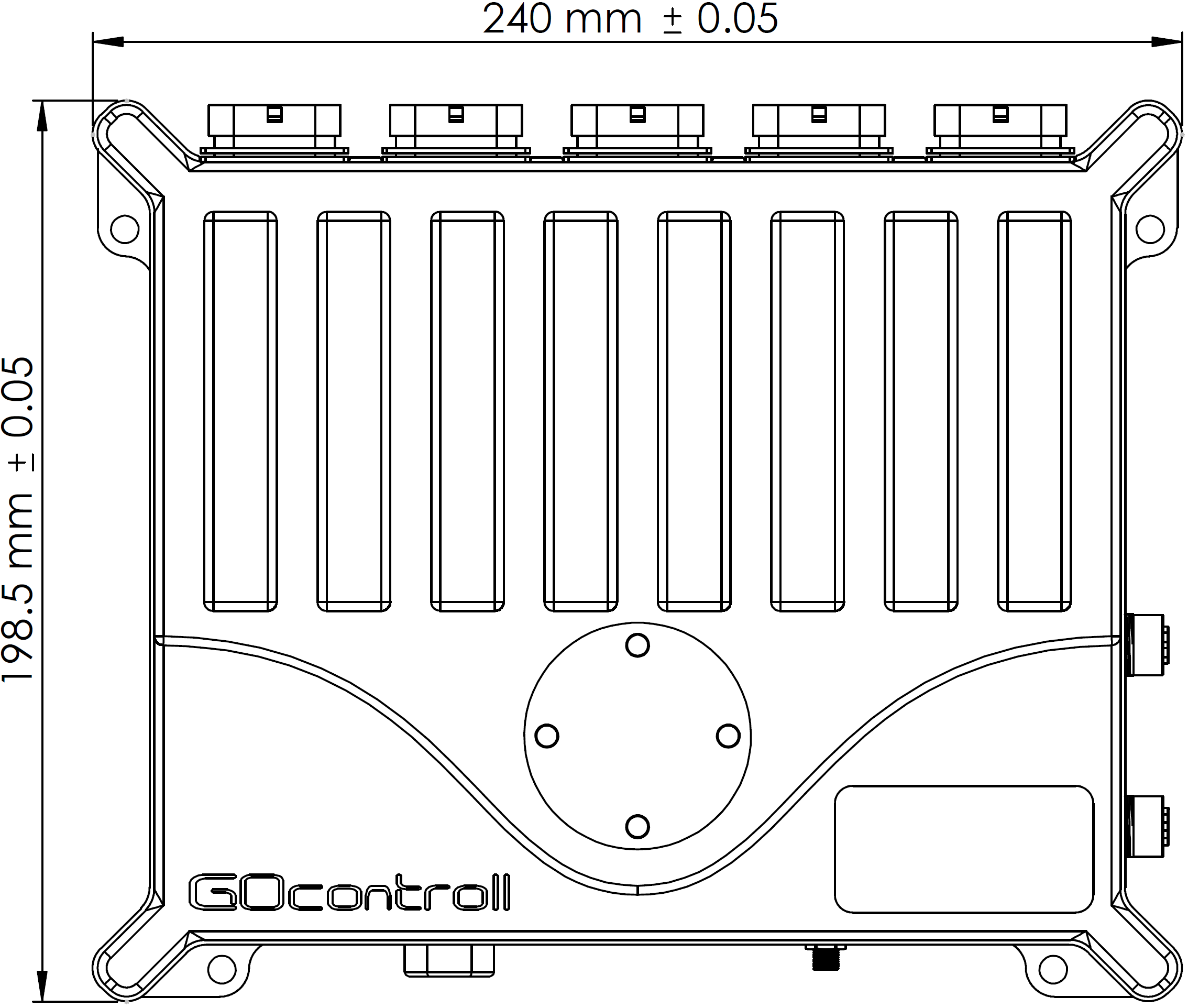
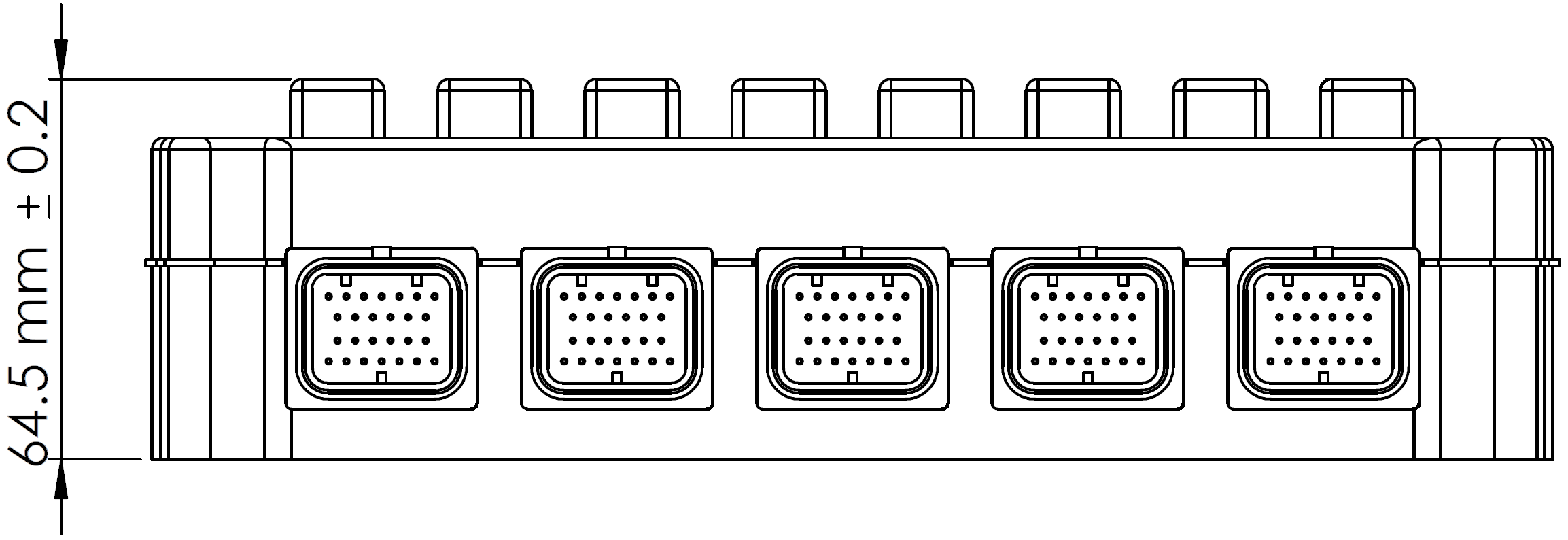
Please let us know if you consider to implement a GOcontroll controller into your system. We can provide a step file for more detailed dimensions.

