The 6 Channel Output Module is a GOcontroll Moduline-compatible expansion card that adds six independently controllable output channels to your modular controller setup. Each output supports multiple configurations, including high-side, low-side, half-bridge, and full-bridge control—making the module ideal for driving a wide range of actuators such as valves, motors, and relays.
All channels are equipped with protection against overcurrent, short circuits, reverse polarity and overheating. In addition, each output includes built-in current measurement, enabling diagnostics and closed-loop control strategies.
Applications
Features
Technical Specifications
The technical specifications are listed in the table below.
| Min | Nom | Max | Unit | |
|---|---|---|---|---|
| Supply rail voltage (normal operation) | 6 | 32 | Volt | |
| Nominal load current for each channel* | 3.5 | A | ||
| Peak load current for each channel* | 4 | A | ||
| Switching frequency (duty cycle selected) | 1 | 10 | kHz | |
| Duty cycle resolution | 0.1 | % |
* The maximum total module current consumption may not exceed 15A.
CAUTION: CONNECTORS MAY NEVER BE HOT PLUGGED! REMOVE POWER BEFORE REMOVING OR INSTALLING CONNECTORS!
Pinout Moduline II, III & IV
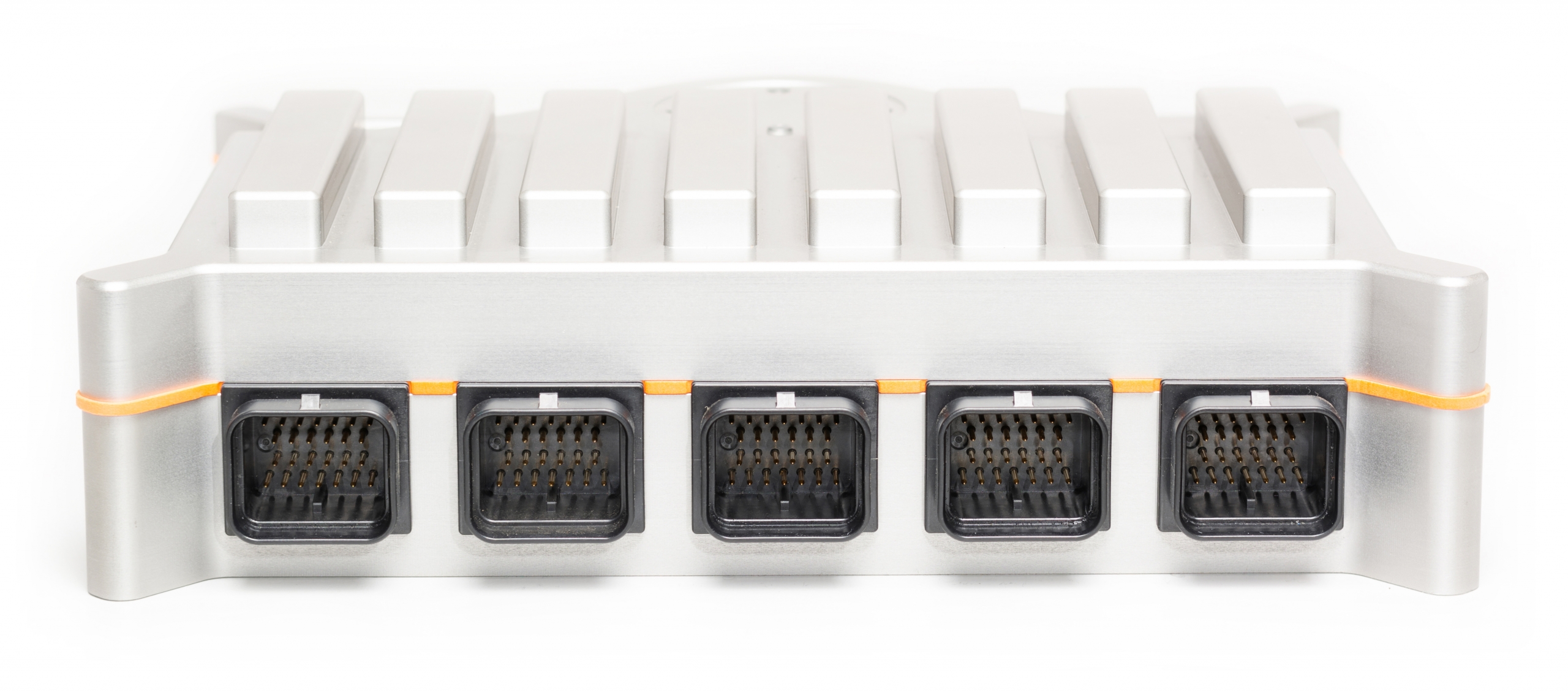
The eight module expansion slots are directed to four connectors in front of the controller. Connector A,B,D and E. If a module is plugged into a specific expansion slot, one half of the corresponding connector is used to interface this module. The picture below gives an overview of the connectors with their related module expansion slots.
Connector C ( in the middle) is used for controller supply and some optional CAN bus connections.
Connector A
Module 1 & 2
Module 3 & 4
System connections
Module 5 & 6
Module 7 & 8
Connector B
Connector C
Connector E
Connector D
The picture below show the connector pinning of the 6 Channel Output module. Be aware of the different pinouts when the module is plugged into even or odd module slots.
Module on even slot

| Pin | Function | Description |
|---|---|---|
| 1 | SUPPLY | Module supply |
| 2 | SUPPLY | Module supply |
| 3 | SUPPLY | Module supply |
| 8 | OUT1 | Signal out 1 |
| 9 | OUT3 | Signal out 3 |
| 10 | OUT5 | Signal out 5 |
| 14 | OUT2 | Signal out 2 |
| 15 | OUT4 | Signal out 4 |
| 16 | OUT6 | Signal out 6 |
| 20 | GROUND | Module ground |
| 21 | GROUND | Module ground |
| 22 | GROUND | Module ground |
Module on uneven slot

| Pin | Function | Description |
|---|---|---|
| 7 | SUPPLY | Module supply |
| 6 | SUPPLY | Module supply |
| 5 | SUPPLY | Module supply |
| 13 | OUT1 | Signal out 1 |
| 12 | OUT3 | Signal out 3 |
| 11 | OUT5 | Signal out 5 |
| 19 | OUT2 | Signal out 2 |
| 18 | OUT4 | Signal out 4 |
| 17 | OUT6 | Signal out 6 |
| 26 | GROUND | Module ground |
| 25 | GROUND | Module ground |
| 24 | GROUND | Module ground |
Pinout Moduline Mini I
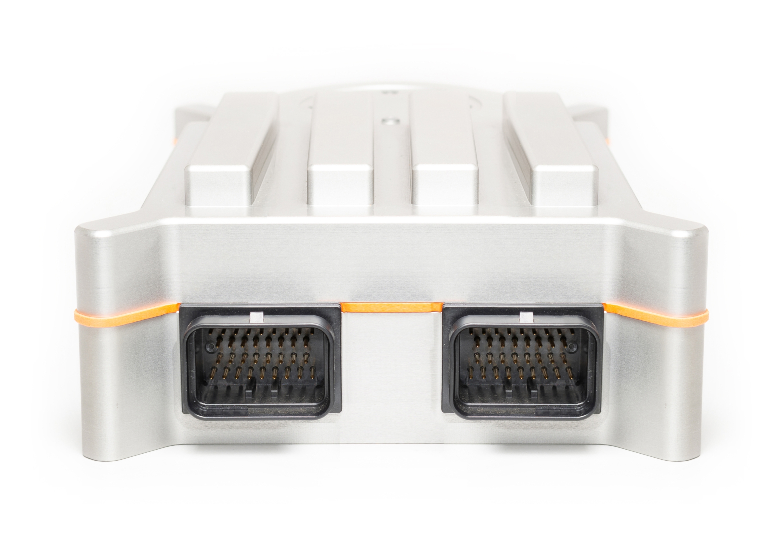
The four module expansion slots are directed to the two main connectors of the controller. Connector A and B. If a module is plugged into a specific expansion slot, one half of the corresponding connector is used to interface this module. The picture below gives an overview of the connectors with their related module expansion slots.
Connector B ( on the left in this view) is also used for controller supply, a controller enable- and reset-input and a CAN bus interface. Connector A also offers a CAN bus interface and on top of that two controller enable inputs.
Module 2 & 1
Module 4 & 3
Connector A
Connector B
The picture below show the connector pinning of the 6 Channel Output module. Be aware of the different pinouts when the module is plugged into even or odd module slots.
Module on even slot

| Pin | Function | Description |
|---|---|---|
| 1 | SUPPLY | Module supply |
| 2 | SUPPLY | Module supply |
| 3 | SUPPLY | Module supply |
| 10 | OUT1 | Signal out 1 |
| 11 | OUT3 | Signal out 3 |
| 12 | OUT5 | Signal out 5 |
| 18 | OUT2 | Signal out 2 |
| 19 | OUT4 | Signal out 4 |
| 20 | OUT6 | Signal out 6 |
| 26 | GROUND | Module ground |
| 27 | GROUND | Module ground |
| 28 | GROUND | Module ground |
Module on uneven slot

| Pin | Function | Description |
|---|---|---|
| 7 | SUPPLY | Module supply |
| 6 | SUPPLY | Module supply |
| 5 | SUPPLY | Module supply |
| 15 | OUT1 | Signal out 1 |
| 14 | OUT3 | Signal out 3 |
| 13 | OUT5 | Signal out 5 |
| 23 | OUT2 | Signal out 2 |
| 22 | OUT4 | Signal out 4 |
| 21 | OUT6 | Signal out 6 |
| 32 | GROUND | Module ground |
| 31 | GROUND | Module ground |
| 30 | GROUND | Module ground |
Be aware to connect all the supply pins and ground pins before controlling any actuator. By connecting only one or two pins, the processor board and module are not able to distribute the amount of current that is required. The processor board and module can be permanently damaged.