2 Channel Power Bridge Module
The 2 Channel Power Bridge Module is a GOcontroll Moduline compatible expansion card designed for high-power actuation. It adds a robust, dual-channel output stage capable of driving inductive or resistive loads using full H-bridge or independent half-bridge configurations.
Each output channel supports continuous currents up to 10 A and peak currents up to 14 A, making it ideal for controlling motors, solenoids, or other heavy-duty actuators. The module allows for high-side, low-side, half bridge and full-bridge switching, all configurable per channel.
Built-in current measurement, over current, reverse polarity, thermal protection, and load dump compliance ensure reliable operation under demanding conditions.
Applications
- Bidirectional DC motor control (forward and reverse via full H-bridge)
- Linear actuator extension and retraction
- Hydraulic and proportional valve actuation
- Pump and fan speed control
- Solenoid, relay and contactor switching
- Heating element and resistive load control
- Current-controlled actuators
Features
- Two independent power output channels
- Usable as a full H-bridge, two independent half bridges, or high-side / low-side switches — on/off or duty-cycle (PWM) controlled
- Configurable PWM switching frequency up to 10 kHz
- Continuous current up to 10 A
- Per-channel current read-out (in high-side configuration)
- Each output is short circuit and over temperature protected
- Module supply is reverse polarity protected
- Module power supply is load dump protected (ISO 7637)
- Bad ground connection detection (earth loop protection)
- External supply voltage range from 8 to 32 Volt
Technical specifications
The technical specifications are listed in the table below.
| Min | Nom | Max | Unit | |
|---|---|---|---|---|
| Supply rail voltage (normal operation) | 8 | 32 | Volt | |
| Nominal load current individual channels | 10 | A | ||
| Peak load current individual channels | 14 | A | ||
| Nominal load current H-bridge configuration | 10 | A | ||
| Peak load current H-bridge configuration | 14 | A | ||
| Switching frequency (duty cycle selected) | 1 | 10 | kHz | |
| Duty cycle resolution | 1 | % |
Connectors may never be hot-plugged. Remove power before removing or installing connectors.
Connect all supply and ground pins before driving an actuator; otherwise the processor board and module can be permanently damaged.
If a safety relay removes the module power, only interrupt the positive supply (+) — never the ground.
The total module current consumption may not exceed 15 A.
Pinout Moduline L4
The eight module expansion slots are directed to four connectors in front of the controller. Connector A,B,D and E. If a module is plugged into a specific expansion slot, one half of the corresponding connector is used to interface this module. The picture below gives an overview of the connectors with their related module expansion slots.
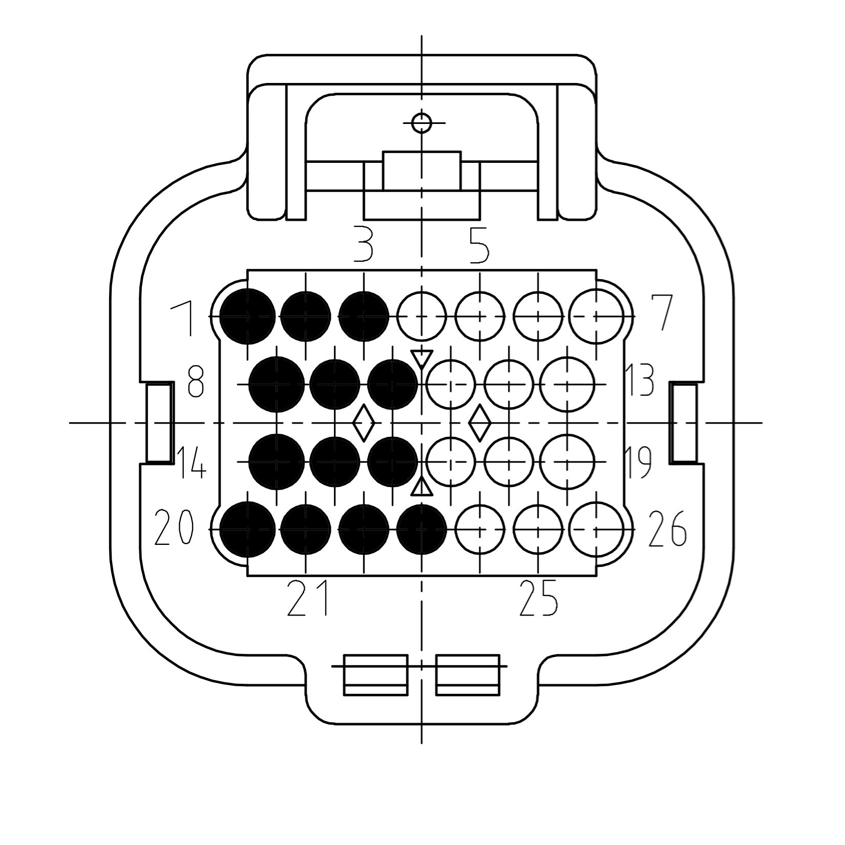
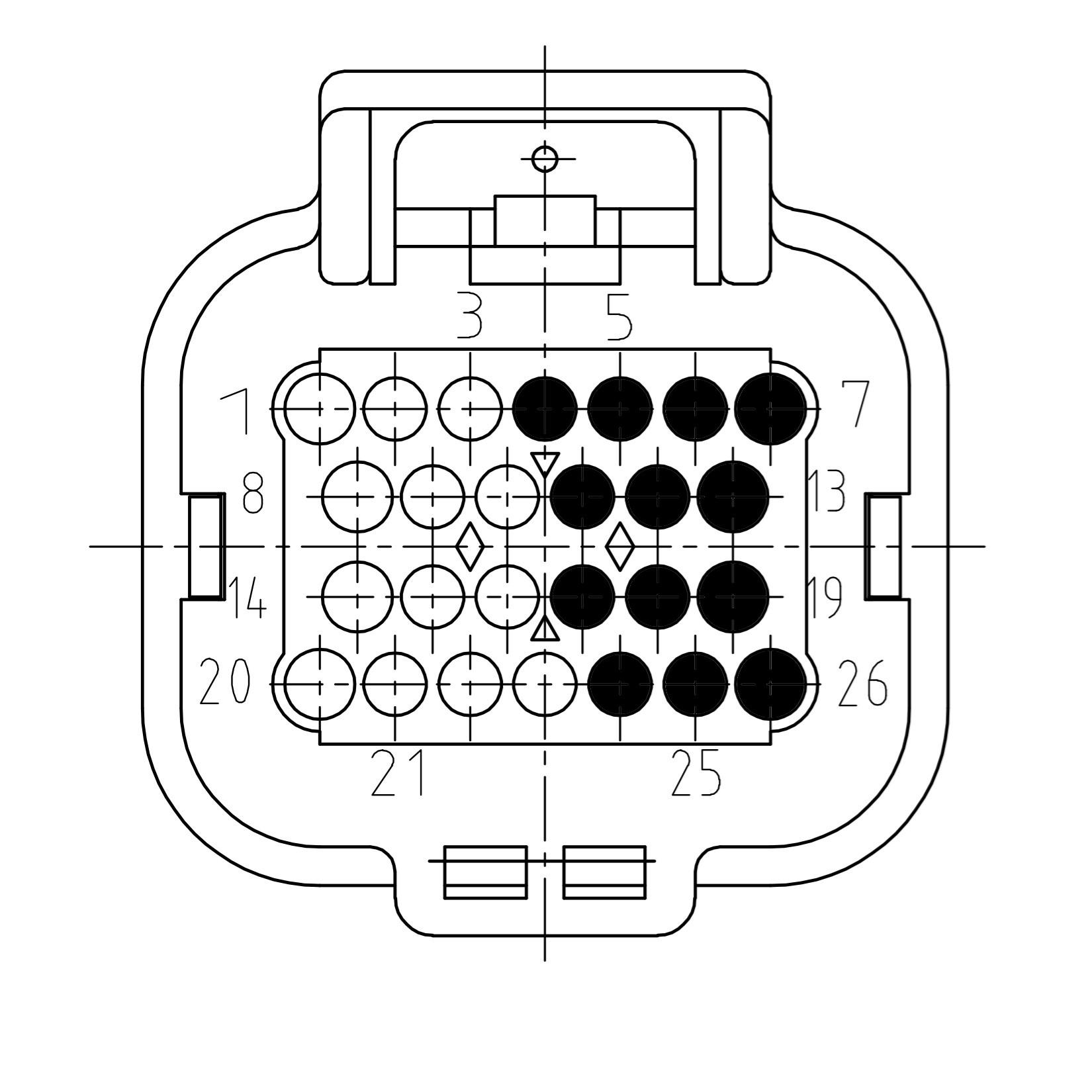
The picture below shows the connector pinning from the 2 Channel Power Bridge Module. Be aware of the different pinouts when the module is plugged into even or odd module slots.
Module on even slot
| Pin | Function | Description |
|---|---|---|
| 1 | SUPPLY | Module supply |
| 2 | SUPPLY | Module supply |
| 3 | SUPPLY | Module supply |
| 8 | OUT1 | Signal out 1 |
| 9 | OUT1 | Signal out 1 |
| 10 | OUT1 | Signal out 1 |
| 14 | OUT2 | Signal out 2 |
| 15 | OUT2 | Signal out 2 |
| 16 | OUT2 | Signal out 2 |
| 20 | GROUND | Module ground |
| 21 | GROUND | Module ground |
| 22 | GROUND | Module ground |
Module on uneven slot
| Pin | Function | Description |
|---|---|---|
| 7 | SUPPLY | Module supply |
| 6 | SUPPLY | Module supply |
| 5 | SUPPLY | Module supply |
| 13 | OUT1 | Signal out 1 |
| 12 | OUT1 | Signal out 1 |
| 11 | OUT1 | Signal out 1 |
| 19 | OUT2 | Signal out 2 |
| 18 | OUT2 | Signal out 2 |
| 17 | OUT2 | Signal out 2 |
| 26 | GROUND | Module ground |
| 25 | GROUND | Module ground |
| 24 | GROUND | Module ground |
Pinout Moduline M1
The four module expansion slots are directed to the two main connectors of the controller. Connector A and B. If a module is plugged into a specific expansion slot, one half of the corresponding connector is used to interface this module. The picture below gives an overview of the connectors with their related module expansion slots.
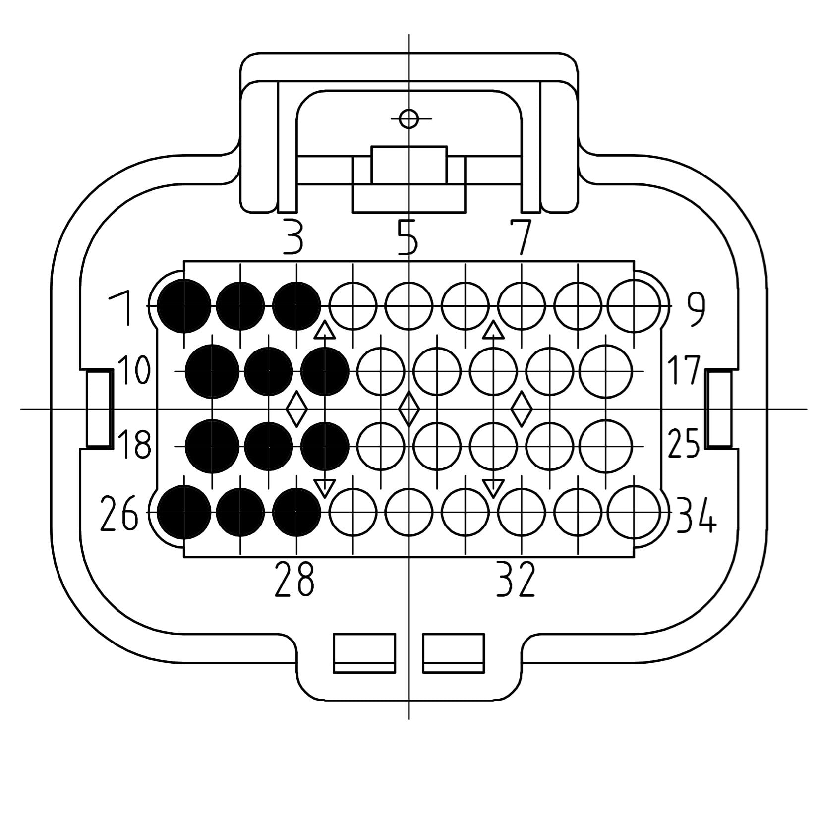
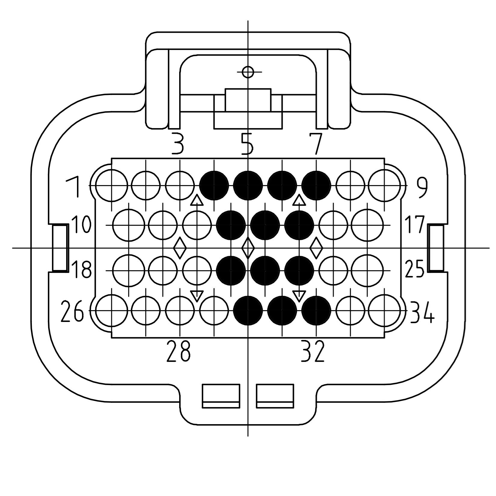
The picture below shows the connector pinning from the 2 Channel Power Bridge Module. Be aware of the different pinouts when the module is plugged into even or odd module slots.
Module on even slot
| Pin | Function | Description |
|---|---|---|
| 1 | SUPPLY | Module supply |
| 2 | SUPPLY | Module supply |
| 3 | SUPPLY | Module supply |
| 10 | OUT1 | Signal out 1 |
| 11 | OUT1 | Signal out 1 |
| 12 | OUT1 | Signal out 1 |
| 18 | OUT2 | Signal out 2 |
| 19 | OUT2 | Signal out 2 |
| 20 | OUT2 | Signal out 2 |
| 26 | GROUND | Module ground |
| 27 | GROUND | Module ground |
| 28 | GROUND | Module ground |
Module on uneven slot
| Pin | Function | Description |
|---|---|---|
| 7 | SUPPLY | Module supply |
| 6 | SUPPLY | Module supply |
| 5 | SUPPLY | Module supply |
| 15 | OUT1 | Signal out 1 |
| 14 | OUT1 | Signal out 1 |
| 13 | OUT1 | Signal out 1 |
| 23 | OUT2 | Signal out 2 |
| 22 | OUT2 | Signal out 2 |
| 21 | OUT2 | Signal out 2 |
| 32 | GROUND | Module ground |
| 31 | GROUND | Module ground |
| 30 | GROUND | Module ground |
Pinout Moduline S1
The two module expansion slots are directed to a single connector on the controller. If a module is plugged into a specific expansion slot, one half of the connector is used to interface this module. The picture below gives an overview of the connector with its related module expansion slots.
The picture below shows the connector pinning from the 2 Channel Power Bridge Module. Be aware of the different pinouts when the module is plugged into the even or the odd module slot.
Module on even slot
| Pin | Function | Description |
|---|---|---|
| 1 | SUPPLY | Module supply |
| 2 | SUPPLY | Module supply |
| 3 | SUPPLY | Module supply |
| 10 | OUT1 | Signal out 1 |
| 11 | OUT1 | Signal out 1 |
| 12 | OUT1 | Signal out 1 |
| 18 | OUT2 | Signal out 2 |
| 19 | OUT2 | Signal out 2 |
| 20 | OUT2 | Signal out 2 |
| 26 | GROUND | Module ground |
| 27 | GROUND | Module ground |
| 28 | GROUND | Module ground |
Module on uneven slot
| Pin | Function | Description |
|---|---|---|
| 7 | SUPPLY | Module supply |
| 6 | SUPPLY | Module supply |
| 5 | SUPPLY | Module supply |
| 15 | OUT1 | Signal out 1 |
| 14 | OUT1 | Signal out 1 |
| 13 | OUT1 | Signal out 1 |
| 23 | OUT2 | Signal out 2 |
| 22 | OUT2 | Signal out 2 |
| 21 | OUT2 | Signal out 2 |
| 32 | GROUND | Module ground |
| 31 | GROUND | Module ground |
| 30 | GROUND | Module ground |
Pinout Moduline HMI1
The two module expansion slots are directed to a single connector on the controller. If a module is plugged into a specific expansion slot, one half of the connector is used to interface this module. The picture below gives an overview of the connector with its related module expansion slots.
The picture below shows the connector pinning from the 2 Channel Power Bridge Module. Be aware of the different pinouts when the module is plugged into the even or the odd module slot.
Module on even slot
| Pin | Function | Description |
|---|---|---|
| 1 | SUPPLY | Module supply |
| 2 | SUPPLY | Module supply |
| 3 | SUPPLY | Module supply |
| 10 | OUT1 | Signal out 1 |
| 11 | OUT1 | Signal out 1 |
| 12 | OUT1 | Signal out 1 |
| 18 | OUT2 | Signal out 2 |
| 19 | OUT2 | Signal out 2 |
| 20 | OUT2 | Signal out 2 |
| 26 | GROUND | Module ground |
| 27 | GROUND | Module ground |
| 28 | GROUND | Module ground |
Module on uneven slot
| Pin | Function | Description |
|---|---|---|
| 7 | SUPPLY | Module supply |
| 6 | SUPPLY | Module supply |
| 5 | SUPPLY | Module supply |
| 15 | OUT1 | Signal out 1 |
| 14 | OUT1 | Signal out 1 |
| 13 | OUT1 | Signal out 1 |
| 23 | OUT2 | Signal out 2 |
| 22 | OUT2 | Signal out 2 |
| 21 | OUT2 | Signal out 2 |
| 32 | GROUND | Module ground |
| 31 | GROUND | Module ground |
| 30 | GROUND | Module ground |