4-20 mA Input Module
The 4–20 mA Input Module is a GOcontroll Moduline-compatible expansion card designed to interface with passive industrial-grade sensors using the 4–20 mA current loop standard. It adds ten current loop input channels to your modular controller, allowing for accurate and reliable acquisition of analog, current loop based process signals.
Each input is equipped with diagnostic capabilities such as wire break detection. The module also features onboard power supplies (Active current loop) and configurable filtering, ensuring stable operation even in electrically noisy environments.
Applications
- Pressure transmitter measurement
- Level transmitter measurement
- Flow transmitter measurement
- Temperature transmitter measurement
- Position and displacement transmitter measurement
- Load and force transmitter measurement
- Interfacing passive (2-wire) 4-20 mA industrial sensors
Features
- Ten 4-20 mA current-loop input channels
- 12-bit measurement resolution across the 4-20 mA range
- Configurable measurement filtering for stable readings in noisy environments
- Protected 16 VDC built in power supply (use with passive sensors)
- Wire break detection on each input
Technical specifications
The technical specifications are listed in the table below.
| Measuring range | Min | Nom | Max | Unit | |
|---|---|---|---|---|---|
| Full scale range | 0 | 25 | mA | ||
| Analog input sample resolution | 4 – 20mA | 12 | Bit | ||
| Analog filter samples | 1 | 1000 | Samples | ||
| Analog input sample frequency | 1 | 10 | kHz | ||
| Sourcing voltage | 15.25 | 16 | 16.75 | V |
Connectors may never be hot-plugged. Remove power before removing or installing connectors.
Pinout Moduline L4
The eight module expansion slots are directed to four connectors in front of the controller. Connector A,B,D and E. If a module is plugged into a specific expansion slot, one half of the corresponding connector is used to interface this module. The picture below gives an overview of the connectors with their related module expansion slots.
The picture below shows the connector pinning from the 4-20 mA Input Module. Be aware of the different pinouts when the module is plugged into even or odd module slots.
Module on even slot
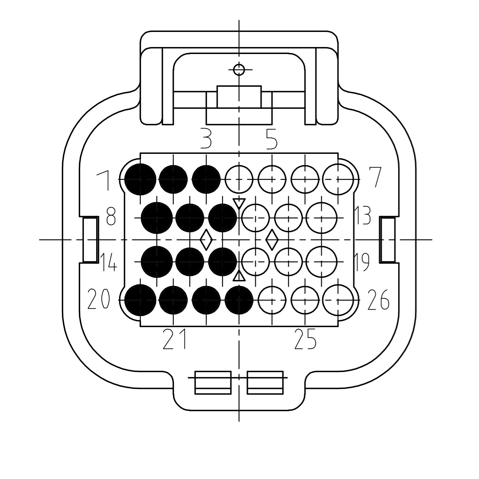
| Pin | Function | Description |
|---|---|---|
| 1 | IN1 | Signal in 1 |
| 2 | IN4 | Signal in 4 |
| 3 | IN7 | Signal in 7 |
| 8 | IN2 | Signal in 2 |
| 9 | IN5 | Signal in 5 |
| 10 | IN8 | Signal in 8 |
| 14 | IN3 | Signal in 3 |
| 15 | IN6 | Signal in 6 |
| 16 | IN9 | Signal in 9 |
| 20 | GROUND | Sensor ground |
| 21 | GROUND | Sensor ground |
| 22 | GROUND | Sensor ground |
| 23 | IN10 | Signal in 10 |
Module on uneven slot
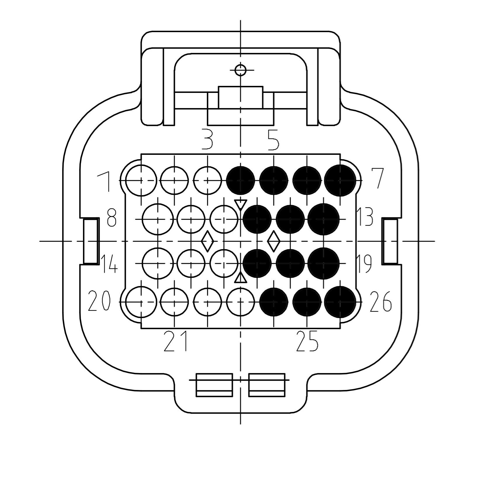
| Pin | Function | Description |
|---|---|---|
| 4 | IN10 | Signal in 10 |
| 5 | IN7 | Signal in 7 |
| 6 | IN4 | Signal in 4 |
| 7 | IN1 | Signal in 1 |
| 11 | IN8 | Signal in 8 |
| 12 | IN5 | Signal in 5 |
| 13 | IN2 | Signal in 2 |
| 17 | IN9 | Signal in 9 |
| 18 | IN6 | Signal in 6 |
| 19 | IN3 | Signal in 3 |
| 24 | GROUND | Sensor ground |
| 25 | GROUND | Sensor ground |
| 26 | GROUND | Sensor ground |
Pinout Moduline M1
The four module expansion slots are directed to the two main connectors of the controller. Connector A and B. If a module is plugged into a specific expansion slot, one half of the corresponding connector is used to interface this module. The picture below gives an overview of the connectors with their related module expansion slots.
The picture below shows the connector pinning from the 4-20 mA Input Module. Be aware of the different pinouts when the module is plugged into even or odd module slots.
Module on even slot
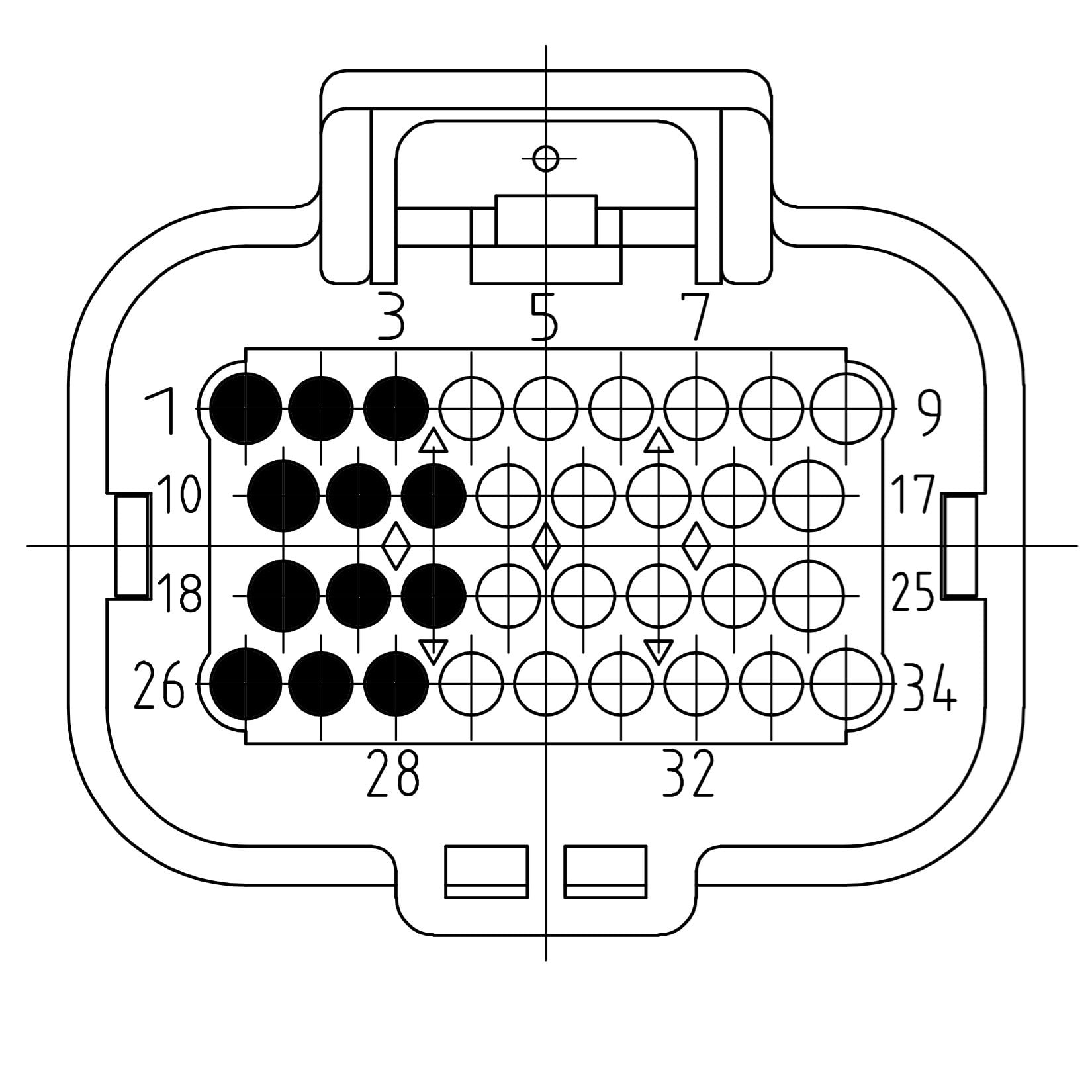
| Pin | Function | Description |
|---|---|---|
| 1 | IN1 | Signal in 1 |
| 2 | IN4 | Signal in 4 |
| 3 | IN7 | Signal in 7 |
| 10 | IN2 | Signal in 2 |
| 11 | IN5 | Signal in 5 |
| 12 | IN8 | Signal in 8 |
| 18 | IN3 | Signal in 3 |
| 19 | IN6 | Signal in 6 |
| 20 | IN9 | Signal in 9 |
| 26 | GROUND | Sensor ground |
| 27 | GROUND | Sensor ground |
| 28 | GROUND | Sensor ground |
| 29 | IN10 | Signal in 10 |
Module on uneven slot
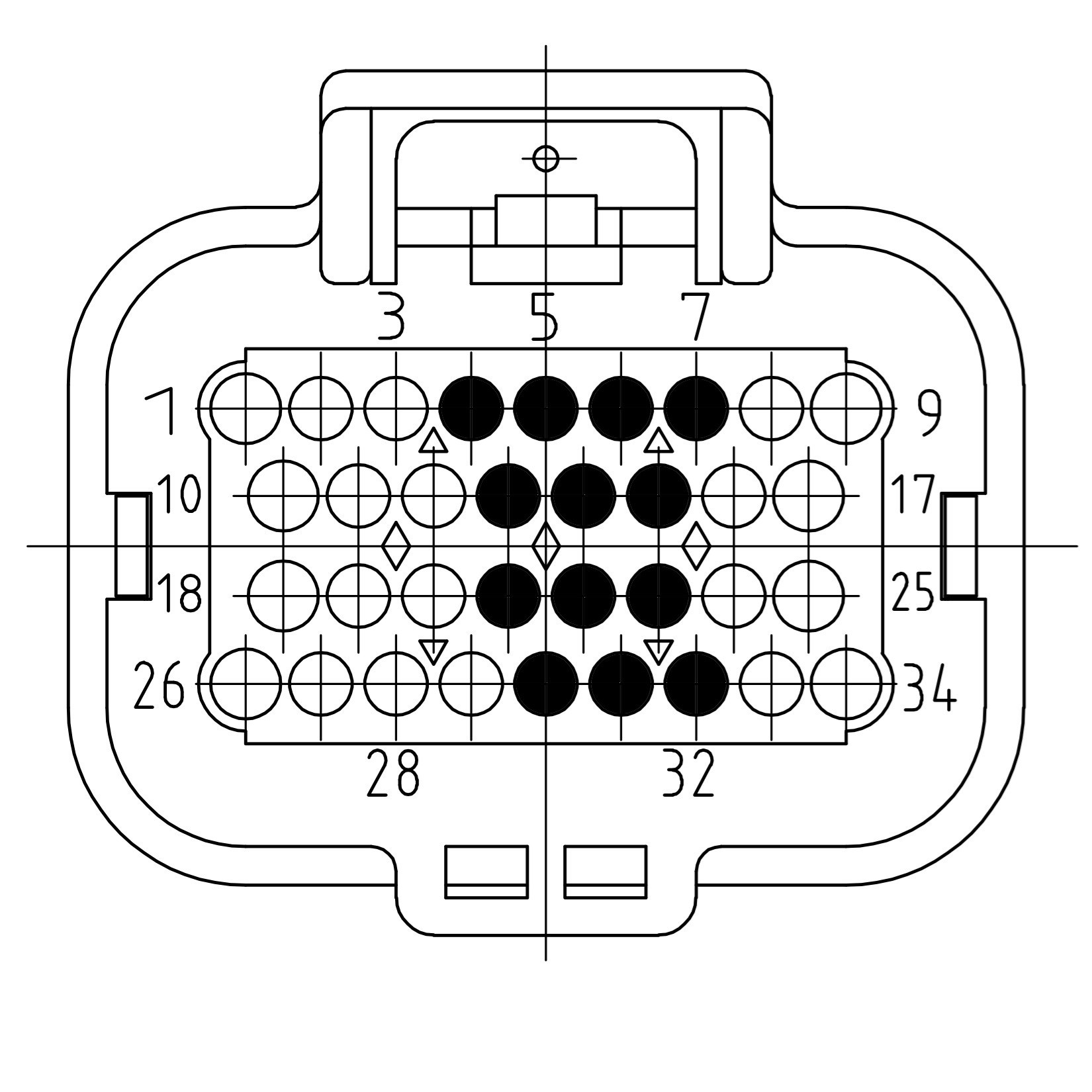
| Pin | Function | Description |
|---|---|---|
| 4 | IN10 | Signal in 10 |
| 5 | IN7 | Signal in 7 |
| 6 | IN4 | Signal in 4 |
| 7 | IN1 | Signal in 1 |
| 13 | IN8 | Signal in 8 |
| 14 | IN5 | Signal in 5 |
| 15 | IN2 | Signal in 2 |
| 21 | IN9 | Signal in 9 |
| 22 | IN6 | Signal in 6 |
| 23 | IN3 | Signal in 3 |
| 30 | GROUND | Sensor ground |
| 31 | GROUND | Sensor ground |
| 32 | GROUND | Sensor ground |
Pinout Moduline S1
The two module expansion slots are directed to a single connector on the controller. If a module is plugged into a specific expansion slot, one half of the connector is used to interface this module. The picture below gives an overview of the connector with its related module expansion slots.
The picture below shows the connector pinning from the 4-20 mA Input Module. Be aware of the different pinouts when the module is plugged into the even or the odd module slot.
Module on even slot
| Pin | Function | Description |
|---|---|---|
| 1 | IN1 | Signal in 1 |
| 2 | IN4 | Signal in 4 |
| 3 | IN7 | Signal in 7 |
| 10 | IN2 | Signal in 2 |
| 11 | IN5 | Signal in 5 |
| 12 | IN8 | Signal in 8 |
| 18 | IN3 | Signal in 3 |
| 19 | IN6 | Signal in 6 |
| 20 | IN9 | Signal in 9 |
| 26 | GROUND | Sensor ground |
| 27 | GROUND | Sensor ground |
| 28 | GROUND | Sensor ground |
| 29 | IN10 | Signal in 10 |
Module on uneven slot
| Pin | Function | Description |
|---|---|---|
| 4 | IN10 | Signal in 10 |
| 5 | IN7 | Signal in 7 |
| 6 | IN4 | Signal in 4 |
| 7 | IN1 | Signal in 1 |
| 13 | IN8 | Signal in 8 |
| 14 | IN5 | Signal in 5 |
| 15 | IN2 | Signal in 2 |
| 21 | IN9 | Signal in 9 |
| 22 | IN6 | Signal in 6 |
| 23 | IN3 | Signal in 3 |
| 30 | GROUND | Sensor ground |
| 31 | GROUND | Sensor ground |
| 32 | GROUND | Sensor ground |
Pinout Moduline HMI1
The two module expansion slots are directed to a single connector on the controller. If a module is plugged into a specific expansion slot, one half of the connector is used to interface this module. The picture below gives an overview of the connector with its related module expansion slots.
The picture below shows the connector pinning from the 4-20 mA Input Module. Be aware of the different pinouts when the module is plugged into the even or the odd module slot.
Module on even slot
| Pin | Function | Description |
|---|---|---|
| 1 | IN1 | Signal in 1 |
| 2 | IN4 | Signal in 4 |
| 3 | IN7 | Signal in 7 |
| 10 | IN2 | Signal in 2 |
| 11 | IN5 | Signal in 5 |
| 12 | IN8 | Signal in 8 |
| 18 | IN3 | Signal in 3 |
| 19 | IN6 | Signal in 6 |
| 20 | IN9 | Signal in 9 |
| 26 | GROUND | Sensor ground |
| 27 | GROUND | Sensor ground |
| 28 | GROUND | Sensor ground |
| 29 | IN10 | Signal in 10 |
Module on uneven slot
| Pin | Function | Description |
|---|---|---|
| 4 | IN10 | Signal in 10 |
| 5 | IN7 | Signal in 7 |
| 6 | IN4 | Signal in 4 |
| 7 | IN1 | Signal in 1 |
| 13 | IN8 | Signal in 8 |
| 14 | IN5 | Signal in 5 |
| 15 | IN2 | Signal in 2 |
| 21 | IN9 | Signal in 9 |
| 22 | IN6 | Signal in 6 |
| 23 | IN3 | Signal in 3 |
| 30 | GROUND | Sensor ground |
| 31 | GROUND | Sensor ground |
| 32 | GROUND | Sensor ground |