Programming with MATLAB Simulink.

All Moduline controllers can be programmed with MATLAB Simulink® . MATLAB Simulink® is a powerful, widely known graphical programming environment which enables the user to program their control algorithms with the help of blocks. MATLAB Simulink® comes with a wide variety of standard blocks for most common interfaces and functions. GOcontroll developed a custom blockset to interface the optional plugin modules and the on-board features. Without the knowledge of code based programming, users are able to build, customize, monitor and maintain their control algorithms.
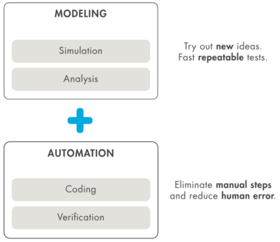
To transform development of complex systems, market-leading companies adopt Model-Based Design by systematically using models throughout the entire process.
- Use a virtual model to simulate and test your system early and often
- Validate your design with physical models, Hardware-in-the-Loop testing, and rapid prototyping
- Generate production-quality C and deploy directly to your embedded system
- Maintain a digital thread with traceability through requirements, system architecture, component design, code and tests
- Extend models to systems in operation to perform predictive maintenance and fault analysis
Code can be generated from within MATLAB Simulink® and directly uploaded to the controller. The compiled MATLAB Simulink® model can be uploaded to the controller in three ways. First of all, models can be directly uploaded during the build process from within MATLAB Simulink® . Node-RED also provides the ability to upload compiled software models with the GOcontroll settings node. Lastly the model can be directly placed into the right folder with a SFTP client like FileZilla.
The MATLAB Simulink environment.
Simulink® is a block diagram environment for multidomain simulation and Model-Based Design. It supports system-level design, simulation, automatic code generation, and continuous test and verification of embedded systems. Simulink provides a graphical editor, customizable block libraries, and solvers for modeling and simulating dynamic systems. It is integrated with MATLAB®, enabling you to incorporate MATLAB algorithms into models and export simulation results to MATLAB for further analysis.
With the GOcontroll blockset, GOcontroll specific function blocks can easily be integrated in the MATLAB Simulink blovk diagram environment. GOcontroll provides a template project with a basic model structure, consisting of an input section, an algorithm section and the output section. This basic model structure provides a solid base upon which your application can be build.


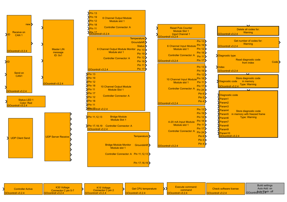
GOcontroll blockset.
GOcontroll created a custom blockset to use directly inside the MATLAB Simulink development environment. These blocks interface the modules plugged in to the controller, and the on-board features. When dragging and dropping nodes into the environment, the user is able to configure a specific feature according user demands by just selecting options.
Configure blocks.
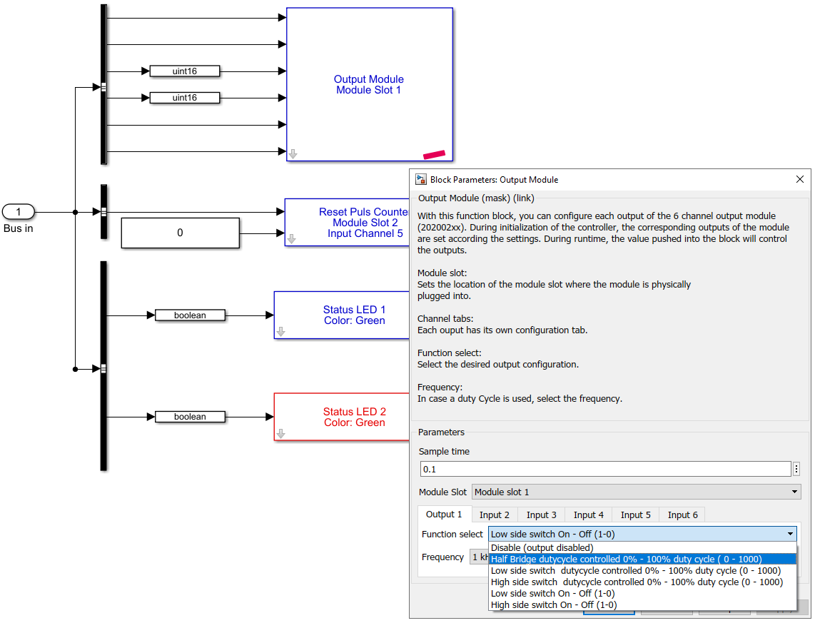
Each custom block that is dragged and dropped into the environment has some configuration options. On the right, an example is given for the output module. When an output module is plugged into the controller, this block can be used to configure the specific behavior of the module.
On the right example:
- Slot on which the module is physically plugged in.
- Sample time which determines the update frequency of the signals.
- Function select determines the functionality of the selected output channel.
An extended explanation of each block can be found in the block library of MATLAB Simulink.

