

Moduline M1
A rugged, Linux-based embedded controller for machine control, monitoring and connectivity in harsh environments
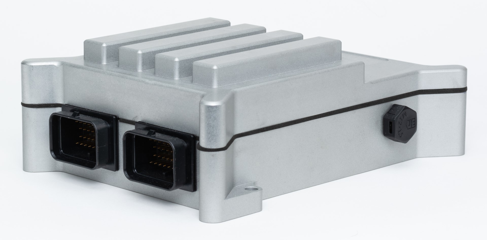
The Moduline M1 is a compact, free-programmable controller built for demanding mobile and industrial applications. This configuration delivers 12 software-configurable input channels and 6 protected power outputs, and adds an expanded set of communication interfaces — RS-232 / RS-485 serial, an additional CAN channel, an IR driver output and two LED driver outputs — alongside dual CAN 2.0B, Ethernet, USB and 4G / Wi-Fi / GPS connectivity. Every input and output is configured graphically in Node-RED or MATLAB/Simulink — no low-level coding required — and the CNC-machined aluminium enclosure is rated IP67 for use in the field.
12 configurable input channels
Each channel is individually configurable as an analogue or digital input, with switchable 5 V sensor supplies, selectable measuring ranges and software pull-up / pull-down. Ideal for interfacing directly with a wide range of sensors.
| Sensor supply | 6× switchable 5 V output |
| Input functions | analogue (mV / 12-bit ADC), digital, frequency, duty cycle, RPM, pulse counter |
| Measuring range | 0–5 V / 0–12 V / 0–24 V (per channel) |
| ADC resolution | 12-bit (0–4095) / 1 mV |
| Frequency range | 1 Hz – 10 kHz |
| Pull-up / pull-down | none / 3.3 kΩ / 4.7 kΩ / 10 kΩ (per channel) |
| Analogue filtering | 0 – 1000 sample averaging |
| Analogue – mV | voltage in mV, scaled to the selected range |
| Analogue – 12-bit | raw ADC value 0 – 4095 |
| Digital | status high / low |
| Frequency | 1 Hz – 10 kHz |
| Duty cycle | low or high time, 0.1 % resolution |
| RPM | rotations per second |
| Pulse counter | continuous pulse count |
6 protected power outputs
Independent power outputs with per-channel current sensing and an adjustable current limit. Each output is short-circuit and over-temperature protected, and suitable for half-bridge, low-/high-side switching, PWM and peak-and-hold actuator control.
| Output functions | half-bridge, low-/high-side (duty or on/off), peak-and-hold, frequency |
| Current limit | 0 – 4000 mA per channel (adjustable) |
| Maximum group current | 15 A |
| PWM frequency | 100 Hz – 10 kHz (per channel pair) |
| Frequency output | 0 – 500 Hz |
| Peak-and-hold | peak 0 – 3500 mA, peak time 0 – 5000 ms |
| Feedback & diagnostics | current (mA), temperature, supply voltage |
| Half-bridge | duty-cycle controlled 0 – 100 % |
| Low-/high-side duty | duty-cycle controlled 0 – 100 % |
| Low-/high-side bool | on / off switching |
| Peak-and-hold | injector control (peak + hold) |
| Frequency output | 0 – 500 Hz |
Processing, power & environment
| Processor | NXP i.MX8M Mini, quad-core ARM Cortex-A53 @ 1.6 GHz |
| RAM | 1 GB |
| Storage (eMMC) | 4 GB |
| Operating system | Linux — MATLAB/Simulink & Node-RED |
| Supply voltage (K30/K15) | 8 – 32 VDC |
| Current consumption | 310 mA @ 12 V / 200 mA @ 24 V |
| Standby current | < 1 mA |
| Load-dump protection | ISO 7637-2, pulse 5a / 5b |
| Operating temperature | −20 °C … +85 °C |
| Housing | EN AW-5083 aluminium, CNC-machined, grey anodised |
| Ingress protection | IP67 |
| Weight (excl. modules) | 651 g |
Communication & system I/O
| Module slots | 4 |
| Status LEDs | 4× RGB |
| CAN | 2× CAN 2.0B |
| Additional CAN | 1× CAN 2.0B |
| Serial | RS-232 / RS-485 |
| IR driver | emitter drive + feedback input |
| LED drivers | 2× (external) |
| USB | USB 2.0 (M12 A-code) |
| Ethernet | 10 / 100 Mbit |
| Motion sensor | 3-axis accelerometer |
| Cellular | 4G / LTE CAT-4 |
| GNSS | GPS / GNSS |
| Wi-Fi | 802.11 b/g/n |
| Bluetooth | Bluetooth 5.1 |
| Configurable I/O | 18 channels (12 in / 6 out) |
| System connectors | Tyco 6437288-1 (A) / 6437288-2 (B) |
| Mating connectors | 4-1437290-0 / 4-1437290-1 |
Where this configuration fits
With 12 sensor inputs, 6 actuator outputs, multi-protocol serial and CAN networking, an IR driver and telematics, this configuration suits control, monitoring and integration tasks across mobile machinery and industrial systems. Typical fields include:
Agricultural machinery
Read position, pressure, temperature and speed sensors on 12 configurable inputs and drive valves, pumps and lighting on 6 power outputs — with CAN networking and GPS for field logging and telematics.
Off-highway & mobile equipment
Interface joystick and sensor signals and control proportional hydraulic valves, auxiliary functions and work lights over CAN, all configured graphically in Node-RED.
Instrumentation & subsystem integration
Bridge third-party instruments and subsystems over RS-232 / RS-485 and the additional CAN channel, drive an IR link and status LEDs, and expose the data to Node-RED for logging and control.
Special & electric vehicles
Body and auxiliary control — lighting, HVAC actuators, pumps — plus multi-bus gateway duties over CAN and serial, and fleet telematics for retrofit and small-series vehicles.
Marine & offshore systems
Monitor engine, tank and environmental sensors, switch pumps and actuators, and stream operational data ashore over cellular for compact onboard control cabinets.
Energy & microgrid
Measure voltages, currents and frequency, switch contactors and relays, and coordinate solar, battery and grid paths with remote monitoring over Ethernet or cellular.
Test benches & R&D
Rapidly prototype measurement and actuation with Node-RED or MATLAB/Simulink, log data over serial and CAN, and build flexible rigs that adapt as requirements change.
Material handling
Control conveyors, sorters and actuators, read encoder and proximity signals, and integrate into plant CAN, serial or Ethernet networks for compact automation nodes.
Pinout — system connectors A & B
Two 34-pin automotive connectors (A & B). Inputs IN1–IN12 are wired to connector A; the six power outputs together with the added serial, additional-CAN, IR-driver and LED-driver interfaces and the controller supply are on connector B.
| Pin | Signal | Description |
|---|---|---|
| B8 | K30 | Supply |
| B9 | K30 | Supply |
| B17 | K15 | Contact 1 (active high) |
| A16 | K15 | Contact 2 (active high) |
| A17 | K15 | Contact 3 (active high) |
| B16 | RESET | Controller reset |
| B24 | CAN 1 LOW | CAN low |
| B25 | CAN 1 HIGH | CAN high |
| A24 | CAN 2 LOW | CAN low |
| A25 | CAN 2 HIGH | CAN high |
| B33 | K31 | Ground |
| B34 | K31 | Ground |
| Signal | Pin | Signal | Pin |
|---|---|---|---|
| SENSOR 5V | A7 | SENSOR 5V | A1 |
| SENSOR 5V | A6 | SENSOR 5V | A2 |
| SENSOR 5V | A5 | SENSOR 5V | A3 |
| IN1 | A15 | IN7 | A10 |
| IN2 | A23 | IN8 | A18 |
| IN3 | A14 | IN9 | A11 |
| IN4 | A22 | IN10 | A19 |
| IN5 | A13 | IN11 | A12 |
| IN6 | A21 | IN12 | A20 |
| SENSOR GND | A32 | SENSOR GND | A26 |
| SENSOR GND | A31 | SENSOR GND | A27 |
| SENSOR GND | A30 | SENSOR GND | A28 |
| Signal | Pin | Signal | Pin |
|---|---|---|---|
| POWER SUPPLY | B7 | SUPPLY | B1 |
| POWER SUPPLY | B6 | SUPPLY | B29 |
| POWER SUPPLY | B5 | RS-232/485 TX | B2 |
| OUT1 | B15 | RS-232/485 RX | B3 |
| OUT2 | B23 | CAN LOW | B27 |
| OUT3 | B14 | CAN HIGH | B28 |
| OUT4 | B22 | IR OUT | B20 |
| OUT5 | B13 | IR IN | B12 |
| OUT6 | B21 | LED A | B11 |
| POWER GROUND | B32 | LED B | B19 |
| POWER GROUND | B31 | GROUND | B26 |
| POWER GROUND | B30 |
Configuration note. The 12 inputs and 6 outputs of article 29110002 are realised with two 6‑Channel Input Modules and one 6‑Channel Output Module, together with an IR Communication Module that provides the RS‑232 / RS‑485 serial, additional CAN, IR-driver and status-LED interfaces, across the controller’s four module slots. The I/O is presented here as a unified 12‑input / 6‑output system; the physical module composition is provided for reference only and does not affect the functional specifications above. The controller has four module slots and can be reconfigured — see gocontroll.com/products for the full module range.