6 Channel Input Module

The 6 channel Input Module is a GOcontroll Moduline compatible expansion card to add 6 general purpose input ports to your modular controller. The inputs are protected and configurable individually for a wide range of applications. The configuration can easily be set by the user in Node-RED.
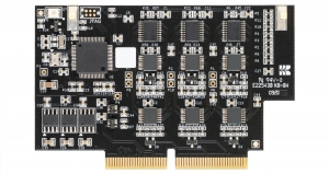
GOcontroll 6 Channel Input Module

 More detailed information about the GOcontroll 6 Channel Input Module.

Learn more >

Model Based Software Development

The GOcontroll Moduline IV controller can be programmed with Node-RED. By easily drag an drop nodes  into the Node-RED environment, no knowlegde about any programming language is needed to build your control system. GOcontroll developed custom nodes for the 6 channel input module. This node enables you to configure each input channel according to your demands using a graphic user interface. The explanation of each configuration can be found in the info section of the node settings.

By double clicking the node, the node settings will open. Here you can configure your 6 channel input module according your demands
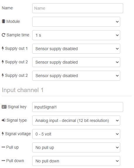
Select the module slot on which the input module is installed to.

  • Module on slot 1
  • Module on slot 2
  • Module on slot 3
  • Module on slot 4
  • Module on slot 5
  • Module on slot 6
  • Module on slot 7
  • Module on slot 8

Specify the way the signals are retrieved from the input module. If the user selects Trigger by inject, the data from each signal is only retrieved when random data is injected in the node by for example the injection node. This can be meaningful during the design of the system. If the sample time is set to a time base, the node will output all signals with the specified sample time.

  • 1 s
  • 200 ms
  • 100 ms
  • 50 ms

Enable or disable sensor supply on selected input channel.

  • Sensor supply disabled
  • Sensor supply enabled

You can configure each input channel according your demands. For example, if you want to measure a rotation speed from an axle, you only have to select this option and tell the module how many pulses he has to count for one rotation. The signal out of the function block holds, in this case, the number of rotations per second.

  • Analog input – decimal (12 bit resolution)
  • Analog input – mV (1 mV resolution)
  • Digtal input – status (high or low)
  • Digtal input – frequency (1Hz to 10 kHz)
  • Digital Input – duty cycle low time (0.1% resolution)
  • Digital Input – duty cycle high time (0.1% resolution)
  • Digital Input – rotation speed (rps)
  • Digital Input – pulse counter in combination with the pairing channel (1&2, 3&4, 5&6)

The module is able to downscale the input voltage to get the highest conversion resolution. Select the range the signal is in between. For example: If the sensor voltage is between 0 and 10V, select the 0 – 12V range for best performance.

  • 0 – 5 volt
  • 0 – 12 volt
  • 0 – 24 volt

If required, pull-up and pull down resistors can be enabled on the input signals. 3 values can be selected.

  • 3.2 kΩ
  • 4.7 kΩ
  • 10 kΩ

If required, pull-up and pull down resistors can be enabled on the input signals. 3 values can be selected.

  • 3.2 kΩ
  • 4.7 kΩ
  • 10 kΩ