2 Channel Power Bridge Module

The 2 channel Power Bridge module is a GOcontroll Moduline IV compatible expansion card to add a high power H-bridge to your modular controller. Instead of single bridge configuration, the module can also be used as 2 high power half bridges.
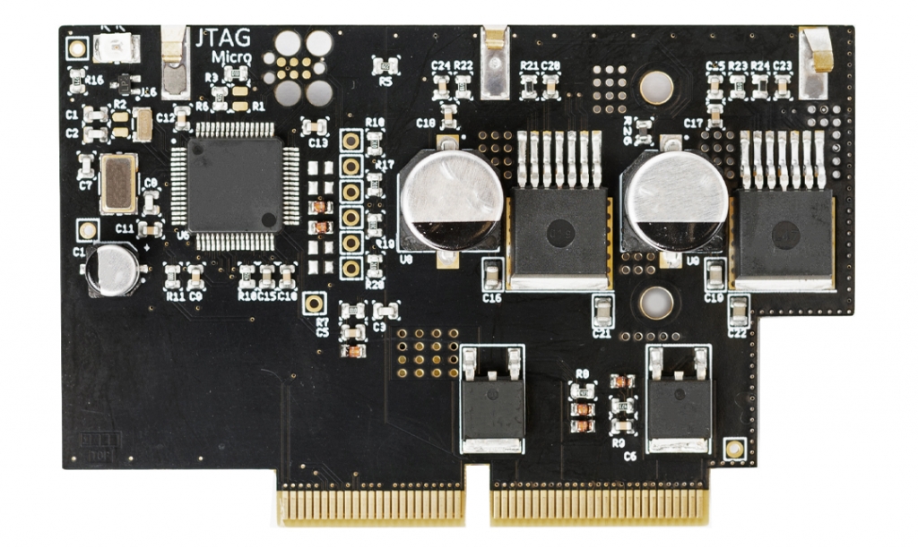
GOcontroll 2 Channel Power Bridge Module

 More detailed information about the GOcontroll 2 Channel Power Bridge Module.

Learn more >

Model Based Software Development

The GOcontroll Moduline IV controller can be programmed with Node-RED. By easily drag an drop nodes  into the Node-RED environment, no knowlegde about any programming language is needed to build your control system. GOcontroll developed custom nodes for the 2 channel power bridge module. This node enables you to configure each output channel according to your demands using a graphic user interface. The explanation of each configuration can be found in the info section of the node settings.

By double clicking the node, the node settings will open. Here you can configure your 2 channel Power Bridge module according your demands
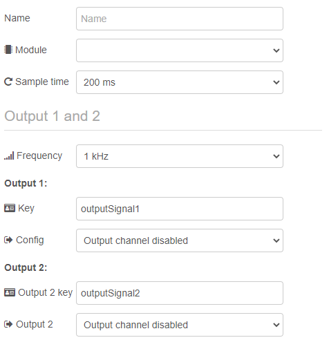
Select the module slot on which the input module is installed to.

  • Module on slot 1
  • Module on slot 2
  • Module on slot 3
  • Module on slot 4
  • Module on slot 5
  • Module on slot 6
  • Module on slot 7
  • Module on slot 8

Specify the way the signals are retrieved from the input module. If the user selects Trigger by inject, the data from each signal is only retrieved when random data is injected in the node by for example the injection node. This can be meaningful during the design of the system. If the sample time is set to a time base, the node will output all signals with the specified sample time.

  • 200 ms
  • 100 ms
  • 50 ms

The switching frequency of the output can be selected. This switching frequency will apply to both output channels.

  • 1 kHz
  • 2 kHz
  • 5 kHz
  • 10 kHz

Here the user can speficy an unique Key for designated output channel.

Each channel (1 -2) can be configured according user demands. Each Output channel has the same options.

Here, the user can select the type of output depending on the actuator that is connected.

  • Output channel disabled
  • Half bridge duty cycle controlled 0 – 100% (0-1000)
  • Low side switch duty cycle controlled 0 – 100% (0-1000)
  • High side switch duty cycle controlled 0 – 100% (0-1000)
  • Low side switch on – off
  • High side switch on – off