Controller pinning
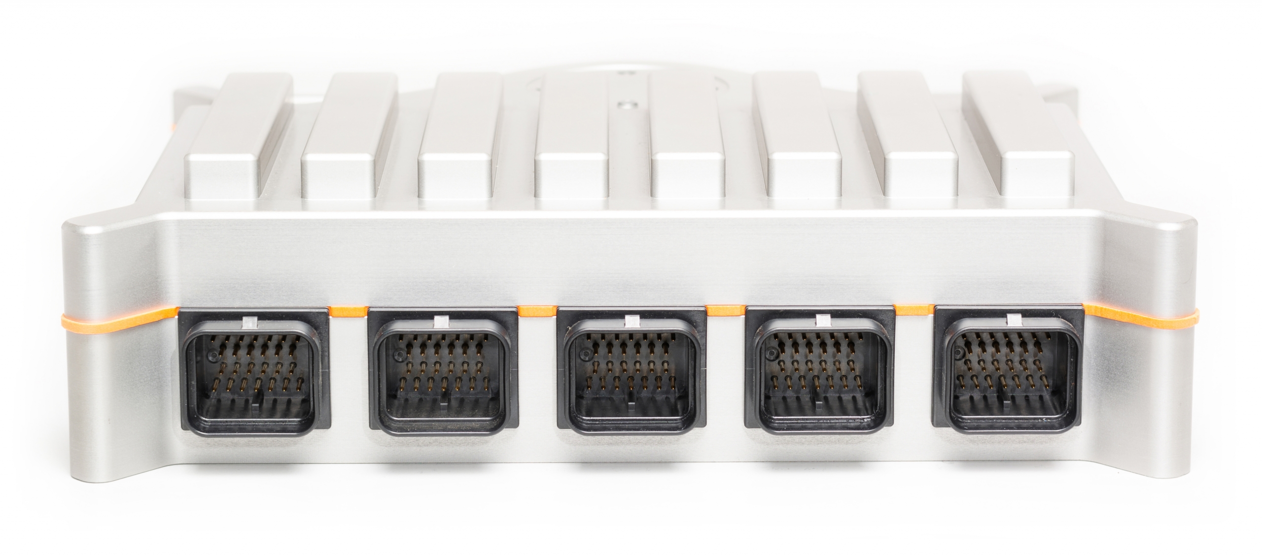
Due to the architecture of the controller, several connector have a dynamic pinning since the pinning depends on the modules that are plugged in. The exact pinning from each connector is described in the datasheet from each module.
Fixed pinning connectors
Communication connectors
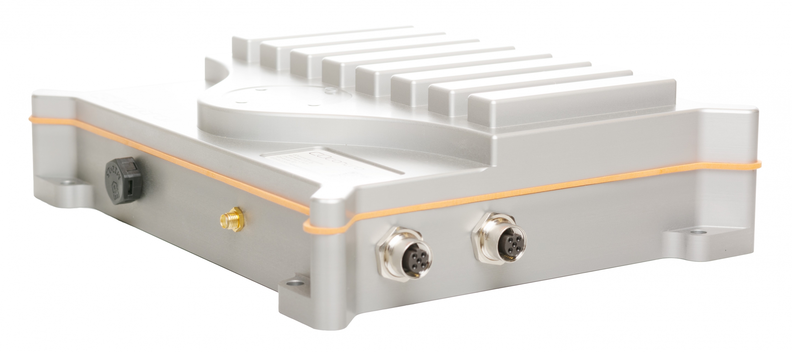
The Moduline is equipped with two M12 connectors for USB and Ethernet connection. The connectors have respectively a B and D code key to prevent connecting the communication buses the wrong way.
USB
Ethernet


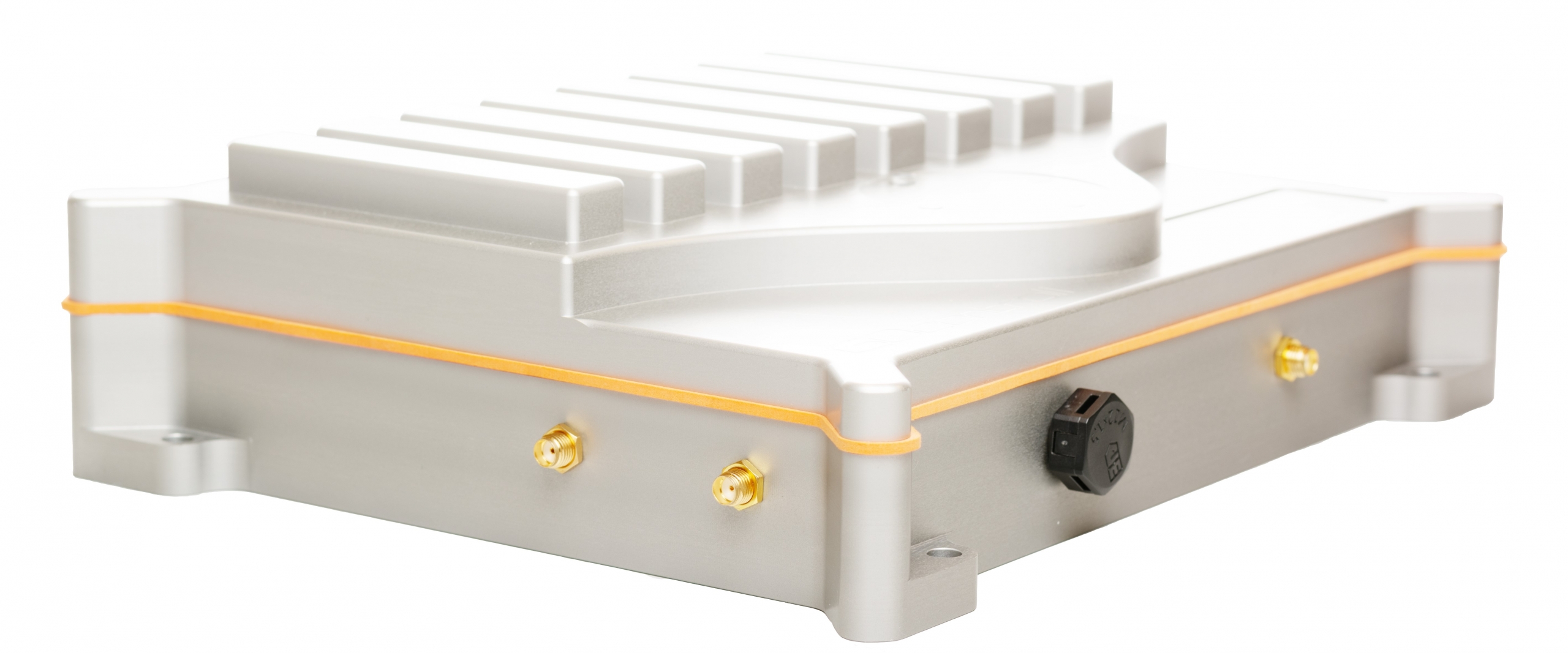
Antenna connector
The Moduline III and IV standard provide WLAN and P2P (2.4ghz) wireless communication. An antenna (included) needs to be placed on the SMA connector of the enclosure
WLAN
GNNS
4G -LTE - NB-IoT
System connector
To power up, it is essential to supply the controller with the system connector (aka C-connector). Beside the supply pins, this connector also provides the onboard communicaion buses such as CAN (2x M-II & M-III, 4x M-IV) and LIN (only M-IV) and the activation pins (1x M-II & M-III, 3x M-IV). The activation pins can wake-up the controller by switching this input to a high level. The voltage applied on these input pins can be read out in Node-RED or Matlab Simulink. For more information, check Control algorithm with Node-RED or Control algorithm with Matlab-Simulink.
Connector A
Module 1 & 2
Module 3 & 4
System connections
Module 5 & 6
Module 7 & 8
Connector B
Connector C
Connector E
Connector D
System C connector
The C connector is used to power up the controller and to connect some communication buses. Since newer Modulines have added features, The pinning of the C connector is slightly different. The pinning can be found on the data page from each controller.
Dynamic pinning connectors
Since the Moduline is a modular controller, the pins from connector A – B – D and E depends on the module that is plugged into a specific slot in the controller. The best way to describe the pinning is by providing an example.
Input Module
The picture below shows the connector pinning from the Input module. Be aware of the different pinouts when the module is plugged into even or odd module slots.

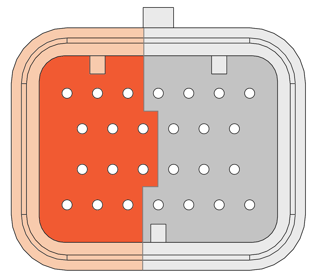
Module located on: 1-3-5-7
Module located on: 2-4-6-8
5V sensor supply
Sensor ground
Signal in 1
Signal in 3
Signal in 5
Signal in 2
Signal in 4
Signal in 6
5V sensor supply
Sensor ground
Signal in 1
Signal in 3
Signal in 5
Signal in 2
Signal in 4
Signal in 6
For example let’s assume an Input Module is plugged into expansion slot 5:
- The corresponding connector is D
- The 5V sensor supply pins are: 5-6-7
- The sensor ground pins are: 24-25-26
- The signal input pins are: 13-19-12-18-11-17
Output Module
The picture below shows the connector pinning from the Output module. Be aware of the different pinouts when the module is plugged into even or odd module slots.
Module located on: 1-3-5-7
Module located on: 2-4-6-8
Module rail supply (internal connected)
Module ground
Channel out 1
Channel out 3
Channel out 5
Channel out 2
Channel out 4
Channel out 6
Module rail supply (internal connected)
Module ground
Channel out 1
Channel out 3
Channel out 5
Channel out 2
Channel out 4
Channel out 6
For example let’s assume an Output Module is plugged into expansion slot 5:
- The corresponding connector is D
- The supply pins are: 5-6-7
- The ground pins are: 24-25-26
- The output channel pins are: 13-19-12-18-11-17
Wiring the connectors
When buying the GOcontroll starter Kit, the plugs, terminals and crimptool are included. The only thing left is connecting it to a proper power source such as a desktop supply or vehicle battery. Make sure to use the right wires which enables you to make a correct crimp connection.
The recommended wire diameter is maximal 0.75 mm²
E.G. Multicomp BS4808
When crimping the terminal on the wire, use the smallest crimping pliers (28-24 AWG)
