
Moduline HMI1
The GOcontroll Moduline HMI1 is a rugged Human Machine Interface controller with a 10.1 inch touch screen, offering up to 2 IO modules.

The HMI1 combines an operator display with machine control in one unit: it shows live values on its touch screen and reads signals and drives outputs through the modules you plug into it. Two module slots let you add the I/O your machine needs, so the modules you fit determine what the controller reads and drives. Everything on the outside runs through one 34-position system connector, two M12 connectors and one SMA connector. For the full specifications and for ordering see the product page.
On this page
At a glance
- Display: 10.1 inch touch screen
- Application processor: i.MX 8M Plus, quad ARM Cortex-A53, 1.6 GHz per core
- Memory: 2 GB LPDDR4 RAM and 8 GB eMMC flash
- Module slots: 2
- Controller enable inputs: 1
- CAN interfaces: 2, CAN 2.0 B and CAN FD
- Ethernet: 10/100 Mbps
- Supply voltage: 8 – 32 VDC
- Temperature range: -20 to 85 °C
- Enclosure: IP67
- Programming: C, MATLAB/Simulink or Node-RED
Module slots
The HMI1 has two module slots, and both are on the system connector. Slot 1 uses thirteen of its positions and slot 2 another thirteen. Every module type has a pin assignment for slot 1 and one for slot 2: the signals are the same, only the pin numbers differ.
The plug-in modules carry the channels of your application, so the modules you fit determine what the controller can measure and control.
Which pin carries which signal depends on the module. Every module page lists its own pinout for each controller and slot: 6 Channel Input Module, 10 Channel Input Module, 4-20 mA Input Module, Loadcell Module, 6 Channel Output Module, 10 Channel Output Module, 2 Channel Power Bridge Module and Multibus Module.
Power supply
You power the controller through the K30 supply pin and the K31 ground pins of the system connector, and you start it with the K15 contact input. The HMI1 has one K30 pin on pin 8, one K15 pin on pin 9, and two K31 ground pins on pins 33 and 34. K15 is active high. This supply powers the controller only.
K30 and K15 both accept 8 – 32 VDC. With the controller active and no modules installed it draws 310 mA at 12 VDC and 200 mA at 24 VDC; with K15 low it draws less than 1 mA. The supply is designed for load dump protection according to ISO7637-2 5a/5b.
K15 is the enable input: pull it high and the controller boots. When your application detects that K15 has gone low it can finish its routines and controls before the controller shuts down. K15 only switches the controller on – the controller draws its power from K30.
Communication interfaces
The 10.1 inch touch screen is the operator interface of the controller.
Two CAN channels connect the HMI1 to the vehicle and machine networks around it, CAN 2.0 B as well as CAN FD. CAN 1 is on pins 16 and 17 of the system connector, CAN 2 on pins 24 and 25.
An Ethernet interface runs at 10/100 Mbps.
The controller has two M12 connectors: one carries Ethernet, the other USB and RS232. The single SMA connector takes the external antenna for Wi-Fi and Bluetooth.
Bluetooth 5.1 (BR/EDR/LE), Wi-Fi 4 (802.11 b/g/n) and RS232 serial communication are available as orderable assembly options.
Connections and pinout
The HMI1 has one system connector with 34 positions. It carries the supply and the CAN connections of the controller as well as both module slots: eight pins are reserved for the controller, thirteen belong to slot 1 and thirteen to slot 2. The two slots are interleaved over the connector, so the pins of a slot are not a single consecutive block. Next to the system connector the controller has two M12 connectors and one SMA connector; those are not part of the pinout below.

On the Moduline HMI1 pin 8 is K30, pin 9 is K15, and pin 33 and pin 34 are both K31.
Connectors may never be hot-plugged: remove power before you remove or install a connector.
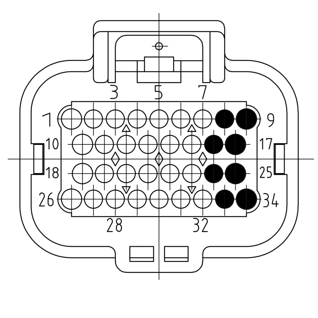
Pins 4-7, 13-15, 21-23 and 30-32 belong to module slot 1; pins 1-3, 10-12, 18-20 and 26-29 to module slot 2. Which signal each pin carries depends on the module fitted. Each module lists its pinout in its own knowledge base article.
| Pin | Signal | Description |
|---|---|---|
| 8 | K30 | Controller supply |
| 9 | K15 | Contact (active high) |
| 16 | CAN 1 LOW | CAN low |
| 17 | CAN 1 HIGH | CAN high |
| 24 | CAN 2 LOW | CAN low |
| 25 | CAN 2 HIGH | CAN high |
| 33 | K31 | Controller ground |
| 34 | K31 | Controller ground |
3D model
The 3D model of the Moduline HMI1 is available as a STEP file in a ZIP archive. Use it to check the fit and the mounting of the controller, and to place it in your own CAD assembly.
Also see
- Supply voltage – the supply limits of the Moduline controllers
- Hot plugging – why connectors are never connected or disconnected under power
- Moduline HMI1 product page – specifications and ordering