
Multibus Module
The Multibus Module is a GOcontroll Moduline compatible expansion card that adds communication interfaces to your Moduline controller.
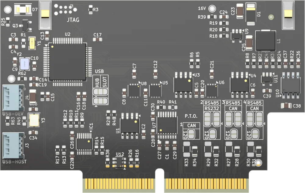
The module puts CAN, RS485 and RS232 buses on the connector of the controller it is plugged into, together with a galvanically isolated isoSPI link to a second Multibus module and a supply for the device you connect. With it you bridge, gateway and route data between the networks in your machine. The module fits every module slot of a Moduline L4, Moduline M1, Moduline S1 or Moduline HMI1. The article number is 203004 followed by two digits for the hardware version. For the electrical specifications see the product page.
On this page
- Communication interfaces
- Connections and pinout
- Module software
- Programming with Node-RED
- Module firmware
Communication interfaces
Three independent CAN FD interfaces connect the module to several vehicle and machine CAN networks.
Three independent RS485 transceivers, switchable one by one, connect half-duplex serial field buses and the RS485 devices and sensors on them.
A galvanically isolated isoSPI channel lets two Multibus modules exchange data across a ground-potential difference, for example between separated sub-systems or between two controllers.
An RS232 interface is available as well, with a transmit and a receive line.
Six pins carry two signals: RS485 1 shares its pins with RS232, RS485 2 with CAN 2, and RS485 3 with CAN 3.
Which signal a shared pair carries is fixed in the hardware of the module, so your application cannot change it and a pair never carries both at once. One module therefore never brings all six interfaces out on its connector – take that into account when you plan the buses of your machine.
One pin is a supply for the sensor or device you connect, and its voltage is configurable. Two more pins are ground.
Connections and pinout
The module presents thirteen pins: one supply pin, ten signal pins and two ground pins. There is no unused pin. Six of the signal pins carry two signals; the tables below name both, and which of the two a module has is fixed in its hardware. Which connector pin carries which signal depends on the controller and on the slot.
Bus termination is a hardware option, for CAN as well as for RS485.
Connectors may never be hot-plugged: remove power before you remove or install a connector.
Pinout Moduline L4
Eight module slots on 26-position connectors. Connector A carries slots 1 and 2, connector B slots 3 and 4, connector D slots 5 and 6, and connector E slots 7 and 8. The pin numbers are the same on all four. Slots 1, 3, 5 and 7 use the uneven layout, slots 2, 4, 6 and 8 the even one.

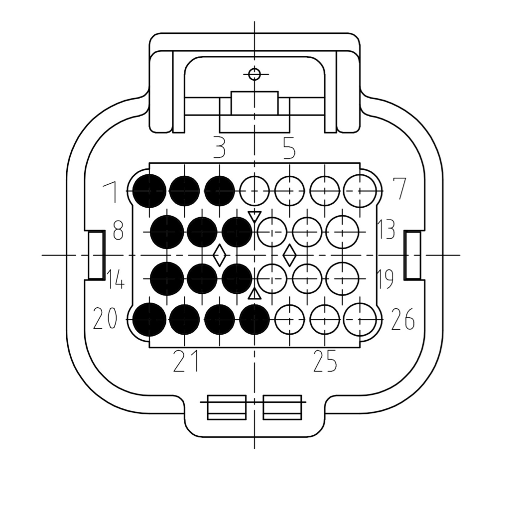
| Signal | Description | Uneven slot | Even slot |
|---|---|---|---|
| SUPPLY | Variable sensor supply | 7 | 1 |
| CAN 1 H | CAN 1 high | 6 | 2 |
| CAN 1 L | CAN 1 low | 5 | 3 |
| RS485 1 B / RS232 OUT | RS485 1 B or RS232 1 out, fixed in hardware | 13 | 8 |
| RS485 1 A / RS232 IN | RS485 1 A or RS232 1 in, fixed in hardware | 12 | 9 |
| RS485 2 B / CAN 2 H | RS485 2 B or CAN 2 high, fixed in hardware | 19 | 14 |
| RS485 2 A / CAN 2 L | RS485 2 A or CAN 2 low, fixed in hardware | 18 | 15 |
| RS485 3 B / CAN 3 H | RS485 3 B or CAN 3 high, fixed in hardware | 25 | 21 |
| RS485 3 A / CAN 3 L | RS485 3 A or CAN 3 low, fixed in hardware | 24 | 22 |
| ISOSPI IP | IP pin of the isoSPI interface | 11 | 10 |
| ISOSPI IM | IM pin of the isoSPI interface | 17 | 16 |
| GROUND | Ground to sensor or device | 26 | 20 |
| GROUND | Ground to sensor or device | 4 | 23 |
Pinout Moduline M1
Four module slots on 34-position connectors. Connector A carries slots 1 and 2, connector B slots 3 and 4. The pin numbers are the same on both. Slots 1 and 3 use the uneven layout, slots 2 and 4 the even one.
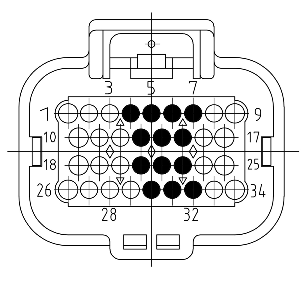
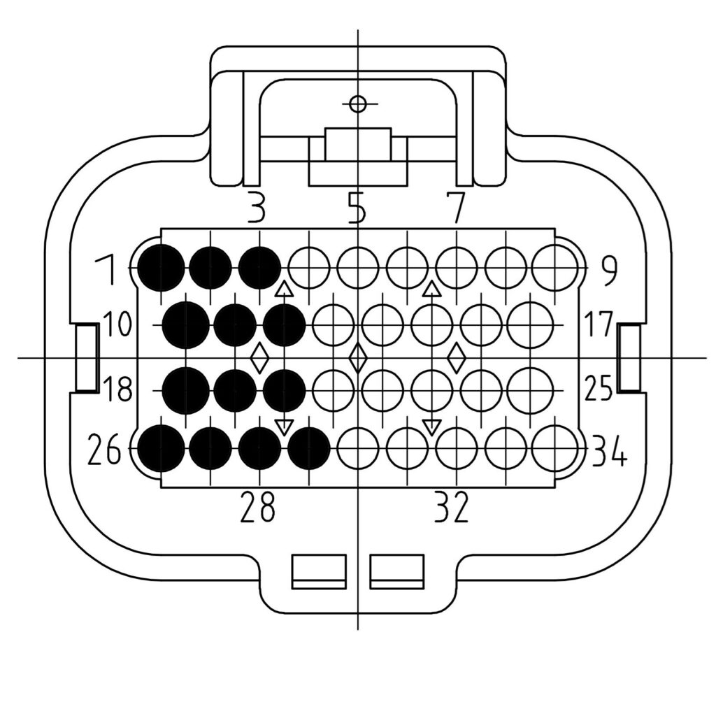
| Signal | Description | Uneven slot | Even slot |
|---|---|---|---|
| SUPPLY | Variable sensor supply | 7 | 1 |
| CAN 1 H | CAN 1 high | 6 | 2 |
| CAN 1 L | CAN 1 low | 5 | 3 |
| RS485 1 B / RS232 OUT | RS485 1 B or RS232 1 out, fixed in hardware | 15 | 10 |
| RS485 1 A / RS232 IN | RS485 1 A or RS232 1 in, fixed in hardware | 14 | 11 |
| RS485 2 B / CAN 2 H | RS485 2 B or CAN 2 high, fixed in hardware | 23 | 18 |
| RS485 2 A / CAN 2 L | RS485 2 A or CAN 2 low, fixed in hardware | 22 | 19 |
| RS485 3 B / CAN 3 H | RS485 3 B or CAN 3 high, fixed in hardware | 31 | 27 |
| RS485 3 A / CAN 3 L | RS485 3 A or CAN 3 low, fixed in hardware | 30 | 28 |
| ISOSPI IP | IP pin of the isoSPI interface | 13 | 12 |
| ISOSPI IM | IM pin of the isoSPI interface | 21 | 20 |
| GROUND | Ground to sensor or device | 32 | 26 |
| GROUND | Ground to sensor or device | 4 | 29 |
Pinout Moduline S1
Two module slots on a single 34-position connector.
| Signal | Description | Slot 1 | Slot 2 |
|---|---|---|---|
| SUPPLY | Variable sensor supply | 7 | 1 |
| CAN 1 H | CAN 1 high | 6 | 2 |
| CAN 1 L | CAN 1 low | 5 | 3 |
| RS485 1 B / RS232 OUT | RS485 1 B or RS232 1 out, fixed in hardware | 15 | 10 |
| RS485 1 A / RS232 IN | RS485 1 A or RS232 1 in, fixed in hardware | 14 | 11 |
| RS485 2 B / CAN 2 H | RS485 2 B or CAN 2 high, fixed in hardware | 23 | 18 |
| RS485 2 A / CAN 2 L | RS485 2 A or CAN 2 low, fixed in hardware | 22 | 19 |
| RS485 3 B / CAN 3 H | RS485 3 B or CAN 3 high, fixed in hardware | 31 | 27 |
| RS485 3 A / CAN 3 L | RS485 3 A or CAN 3 low, fixed in hardware | 30 | 28 |
| ISOSPI IP | IP pin of the isoSPI interface | 13 | 12 |
| ISOSPI IM | IM pin of the isoSPI interface | 21 | 20 |
| GROUND | Ground to sensor or device | 32 | 26 |
| GROUND | Ground to sensor or device | 4 | 29 |
Pinout Moduline HMI1
Two module slots on a single 34-position connector.
| Signal | Description | Slot 1 | Slot 2 |
|---|---|---|---|
| SUPPLY | Variable sensor supply | 7 | 1 |
| CAN 1 H | CAN 1 high | 6 | 2 |
| CAN 1 L | CAN 1 low | 5 | 3 |
| RS485 1 B / RS232 OUT | RS485 1 B or RS232 1 out, fixed in hardware | 15 | 10 |
| RS485 1 A / RS232 IN | RS485 1 A or RS232 1 in, fixed in hardware | 14 | 11 |
| RS485 2 B / CAN 2 H | RS485 2 B or CAN 2 high, fixed in hardware | 23 | 18 |
| RS485 2 A / CAN 2 L | RS485 2 A or CAN 2 low, fixed in hardware | 22 | 19 |
| RS485 3 B / CAN 3 H | RS485 3 B or CAN 3 high, fixed in hardware | 31 | 27 |
| RS485 3 A / CAN 3 L | RS485 3 A or CAN 3 low, fixed in hardware | 30 | 28 |
| ISOSPI IP | IP pin of the isoSPI interface | 13 | 12 |
| ISOSPI IM | IM pin of the isoSPI interface | 21 | 20 |
| GROUND | Ground to sensor or device | 32 | 26 |
| GROUND | Ground to sensor or device | 4 | 29 |
Note: the module fits every controller slot shown above. The go-multibus service and its tools run on the Linux based Moduline controllers: the Moduline L4, the Moduline M1 and the Moduline HMI1.
Module software
The go-multibus package brings a Multibus module up after a controller boot and publishes what it reads. It is one package with two faces: a background service and a terminal tool.
Install the package from the GOcontroll apt repository.
apt-get install go-multibusThen enable the service, so that it also starts at every boot.
systemctl enable --now go-multibusThe service resets the module, starts its application, configures the interfaces over SPI, waits for USB and then runs. Every step is idempotent, and the sequence restarts when a module disappears. Removing a module and putting it back therefore recovers on its own.
The module reaches the controller over USB. When the OTG port of a controller is still in device mode, the package switches it to host mode. That controller then needs one reboot before a module enumerates.
Ask the service what it is doing:
go-multibus statusRunning go-multibus without a subcommand opens a terminal interface for commissioning. Only one program may hold the module at a time, so the interface refuses to start while the service runs.
Bus parameters such as the bitrate belong to go-can, not to go-multibus.
The Multibus module is the isoSPI master. It polls the battery side over one twisted pair, and that side only answers. The module keeps its own latest snapshot, so a read from the controller never waits for a battery round.
The service reads that snapshot over USB twice per second. By default it writes the result to /dev/shm/gocontroll/multibus-cells.json. The file is replaced atomically, so a reader always sees one complete document and needs no locking. It lives in memory and is cleared on reboot.
Branch on valid. It is true only when the isoSPI link is up and the sample is fresh.
Cell voltages appear twice, on purpose. cells_v is rounded for display. cells_100uv carries the raw device value in units of 100 µV, so 36000 is 3.6000 V.
age_ms tells you how old the module’s answer is. The module sets the simulated flag itself, so simulated data never passes for a real measurement.
If valid stays false, check the isoSPI link counters:
gocontroll-cellmon statusFor a readable snapshot of the cells themselves:
gocontroll-cellmon cellsProgramming with Node-RED
An example flow reads the published cell data and turns it into a Node-RED message. It reads the JSON document every 500 ms and checks the valid field, so that stale samples get their own output. A small function node picks out the first cell as an example.
The flow uses the standard file in and json nodes. Note: the GOcontroll Read-Memory node cannot read this document. That node reads one value per file, so a JSON document gives it nothing to send.
Download the archive, unpack it and open node-red-multibus-cells.json:
Copy the contents of that file. Then choose Import and clipboard in the Node-RED menu, paste the text and click Import.
Module firmware
The module carries its own firmware. You update it with go-modules, like any other module.
Also see
- Hot plugging – why connectors are never connected or disconnected under power
- Multibus Module product page – specifications and ordering