
Loadcell Module
The Loadcell Module is a GOcontroll Moduline compatible expansion card that interfaces directly with load cells and strain-gauge sensors.
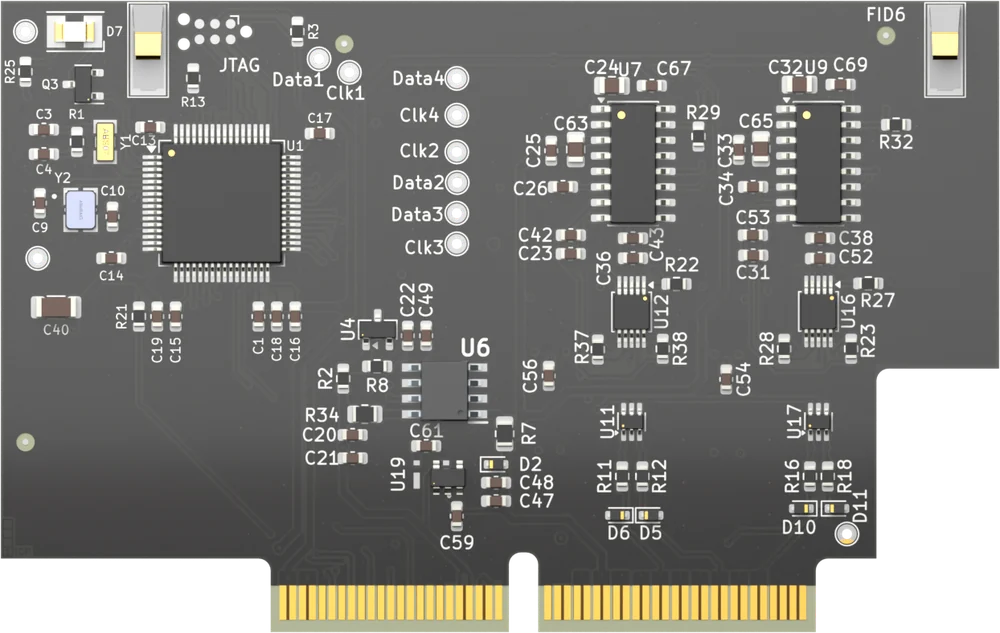
The module has four differential channels for resistive strain gauge bridges, and two excitation lines that supply the load cells you connect. Every channel has its own gain, sample rate and sensitivity setting, and a tare function to set its zero point. The module fits every module slot of a Moduline L4, Moduline M1, Moduline S1 or Moduline HMI1. The article number is 201005 followed by two digits for the hardware version. For the specifications see the product page.
On this page
Channels and configuration
The module has four load cell channels. Each channel is a differential input for a resistive strain gauge bridge and has a positive and a negative signal pin of its own. The two excitation lines EXC 1 and EXC 2 are shared by all four channels and supply the connected load cells.
Each channel is configured on its own, with four settings:
- Gain – the gain of the analog to digital converter: 32, 64 or 128.
- Sample rate – how often the channel is converted: 10 or 80 Hz.
- Sensitivity – raw, 1 mV/V, 2 mV/V or 3 mV/V. In raw mode the channel returns the raw converter count. In the mV/V modes you pick the value that matches the rated output of the load cell you connected.
- Full scale – the full scale value of that load cell. The module firmware uses it to scale the reading in the mV/V modes, and ignores it in raw mode.
The module returns one signed value per channel. Every channel also has a tare function that sets its zero point, and the tare value you send is in the same unit as the reading of that channel.
Connections and pinout
The module presents the two excitation lines EXC 1 and EXC 2, the four load cell inputs LC 1 to LC 4 with a positive and a negative pin each, two sensor ground pins and one pin without a function. Which connector pin carries which signal depends on the controller and on the slot.
If more supply or ground connections are needed than the module has pins, the wires can be spliced.
Connectors may never be hot-plugged: remove power before you remove or install a connector.
Pinout Moduline L4
Eight module slots on 26-position connectors. Connector A carries slots 1 and 2, connector B slots 3 and 4, connector D slots 5 and 6, and connector E slots 7 and 8. The pin numbers are the same on all four. Slots 1, 3, 5 and 7 use the uneven layout, slots 2, 4, 6 and 8 the even one.
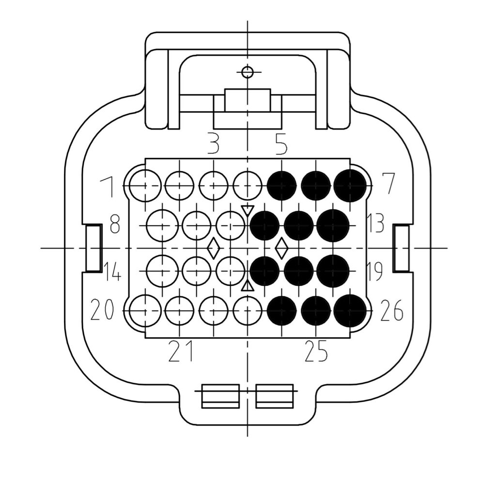
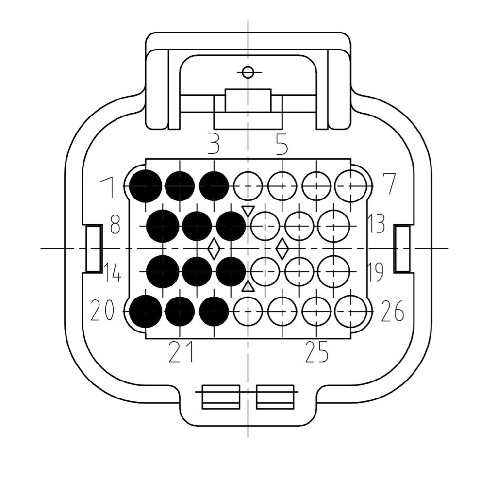
| Signal | Description | Uneven slot | Even slot |
|---|---|---|---|
| EXC 1 | Excitation voltage 1 | 7 | 1 |
| EXC 2 | Excitation voltage 2 | 6 | 2 |
| LC 1+ | Loadcell 1 positive | 13 | 8 |
| LC 1- | Loadcell 1 negative | 19 | 14 |
| LC 2+ | Loadcell 2 positive | 12 | 9 |
| LC 2- | Loadcell 2 negative | 18 | 15 |
| LC 3+ | Loadcell 3 positive | 5 | 3 |
| LC 3- | Loadcell 3 negative | 11 | 10 |
| LC 4+ | Loadcell 4 positive | 17 | 16 |
| LC 4- | Loadcell 4 negative | 24 | 22 |
| GROUND | Sensor ground | 26 | 20 |
| GROUND | Sensor ground | 25 | 21 |
| NC | No functionality | 4 | 23 |
Pinout Moduline M1
Four module slots on 34-position connectors. Connector A carries slots 1 and 2, connector B slots 3 and 4. The pin numbers are the same on both. Slots 1 and 3 use the uneven layout, slots 2 and 4 the even one.
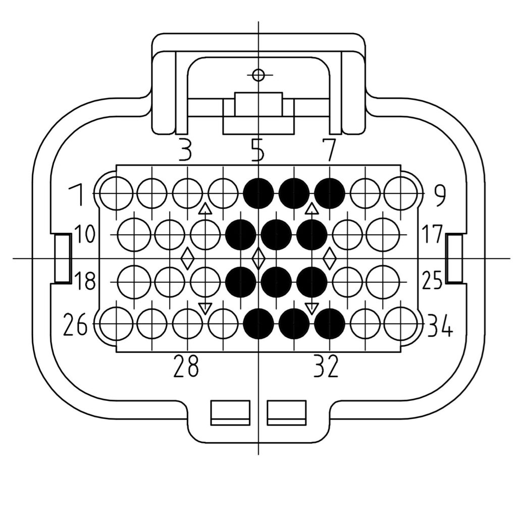
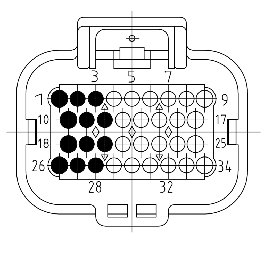
| Signal | Description | Uneven slot | Even slot |
|---|---|---|---|
| EXC 1 | Excitation voltage 1 | 7 | 1 |
| EXC 2 | Excitation voltage 2 | 6 | 2 |
| LC 1+ | Loadcell 1 positive | 15 | 10 |
| LC 1- | Loadcell 1 negative | 23 | 18 |
| LC 2+ | Loadcell 2 positive | 14 | 11 |
| LC 2- | Loadcell 2 negative | 22 | 19 |
| LC 3+ | Loadcell 3 positive | 5 | 3 |
| LC 3- | Loadcell 3 negative | 13 | 12 |
| LC 4+ | Loadcell 4 positive | 21 | 20 |
| LC 4- | Loadcell 4 negative | 30 | 28 |
| GROUND | Sensor ground | 32 | 26 |
| GROUND | Sensor ground | 31 | 27 |
| NC | No functionality | 4 | 29 |
Pinout Moduline S1
Two module slots on a single 34-position connector.
| Signal | Description | Slot 1 | Slot 2 |
|---|---|---|---|
| EXC 1 | Excitation voltage 1 | 7 | 1 |
| EXC 2 | Excitation voltage 2 | 6 | 2 |
| LC 1+ | Loadcell 1 positive | 15 | 10 |
| LC 1- | Loadcell 1 negative | 23 | 18 |
| LC 2+ | Loadcell 2 positive | 14 | 11 |
| LC 2- | Loadcell 2 negative | 22 | 19 |
| LC 3+ | Loadcell 3 positive | 5 | 3 |
| LC 3- | Loadcell 3 negative | 13 | 12 |
| LC 4+ | Loadcell 4 positive | 21 | 20 |
| LC 4- | Loadcell 4 negative | 30 | 28 |
| GROUND | Sensor ground | 32 | 26 |
| GROUND | Sensor ground | 31 | 27 |
| NC | No functionality | 4 | 29 |
Pinout Moduline HMI1
Two module slots on a single 34-position connector.
| Signal | Description | Slot 1 | Slot 2 |
|---|---|---|---|
| EXC 1 | Excitation voltage 1 | 7 | 1 |
| EXC 2 | Excitation voltage 2 | 6 | 2 |
| LC 1+ | Loadcell 1 positive | 15 | 10 |
| LC 1- | Loadcell 1 negative | 23 | 18 |
| LC 2+ | Loadcell 2 positive | 14 | 11 |
| LC 2- | Loadcell 2 negative | 22 | 19 |
| LC 3+ | Loadcell 3 positive | 5 | 3 |
| LC 3- | Loadcell 3 negative | 13 | 12 |
| LC 4+ | Loadcell 4 positive | 21 | 20 |
| LC 4- | Loadcell 4 negative | 30 | 28 |
| GROUND | Sensor ground | 32 | 26 |
| GROUND | Sensor ground | 31 | 27 |
| NC | No functionality | 4 | 29 |
Note: only one application may claim the modules. If a second program initialises the same module – most often a compiled Simulink model next to a Node-RED flow – it causes strange behaviour. Use the CodeBase, Simulink or Node-RED, not two of them at the same time.
Programming with the CodeBase
The GOcontroll CodeBase is the C library you use to write your own program for a Moduline controller. The Loadcell Module is handled by the functions in GO_module_loadcell.h and by one _loadcellModule instance per module.
The order of the calls matters. Set the module type before you configure a channel, initialise the communication before you assign the slot, and configure the channels before you send the configuration:
static _loadcellModule loadcellModule;

GO_board_get_hardware_version();
GO_module_loadcell_set_module_type(&loadcellModule, LOADCELLMODULE);
GO_communication_modules_initialize(MODULESLOT1);
GO_module_loadcell_set_module_slot(&loadcellModule, MODULESLOT1);

for (uint8_t ch = LOADCELLCHANNEL1; ch <= LOADCELLCHANNEL4; ch++) {
    GO_module_loadcell_configure_channel(&loadcellModule, ch,
                                         LOADCELLGAIN_128,
                                         LOADCELLDATARATE_80,
                                         LOADCELLSENSITIVITY_2MVV,
                                         fullScale);
}

GO_module_loadcell_configuration(&loadcellModule);
Be aware that GO_communication_modules_initialize() must be called before GO_module_loadcell_set_module_slot(). The initialize call fills the module occupancy data, and set_module_slot uses that data to verify that a Loadcell Module is really present in the slot. In the other order you get a contested slot error at runtime.
The last parameter of GO_module_loadcell_configure_channel() is the full scale value of the load cell on that channel. All four settings stay in the struct until GO_module_loadcell_configuration() sends them to the module in one frame, so configure every channel you use before you call it.
Reading the module is one call in your application loop. The results are in the value array, one entry per channel:
GO_module_loadcell_receive_values(&loadcellModule);

/* loadcellModule.value[0] .. loadcellModule.value[3] hold channel 1 .. 4 */
Leave at least 10 ms between two reads of the same module.
A channel is zeroed with GO_module_loadcell_tare(). That call is edge triggered: it only sends a frame when the trigger you pass differs from the one it stored the previous time, so toggle the trigger between 0 and 1 for every tare you want.
Also see
- 6 Channel Input Module – six inputs with a selectable reading range up to 24 V and a function to select per channel
- Hot plugging – removing and inserting a module
- Loadcell Module product page – specifications and ordering