
10 Channel Output Module
The 10 Channel Output Module is a GOcontroll Moduline compatible expansion card that adds ten high side output ports to your Moduline controller.
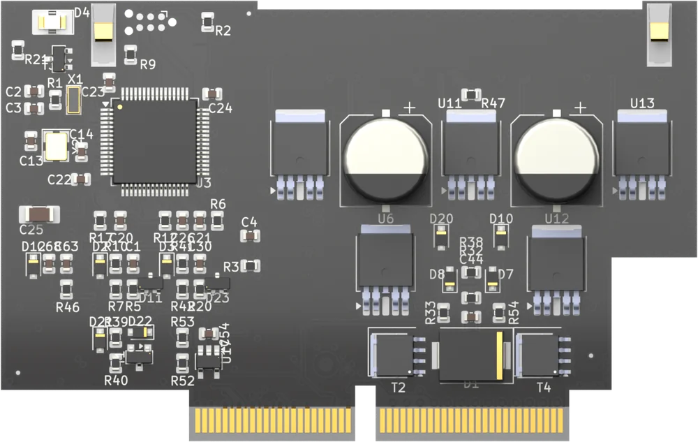
Each channel switches the module supply through to its load, either on and off or duty cycle controlled, and is configured on its own. The module fits every module slot of a Moduline L4, Moduline M1, Moduline S1 or Moduline HMI1. The article number is 202003 followed by two digits for the hardware version. For the electrical specifications see the product page.
On this page
- Channels and configuration
- Connections and pinout
- Programming with the CodeBase
- Programming with Simulink
- Programming with Node-RED
- Module firmware
Channels and configuration
You set the function of each channel. The function determines how the channel drives its load, and what the value you send to it means:
- Output channel disabled: the driver of the channel is switched off. This is the default for every channel, so a module that has just been scanned drives nothing.
- High side switch duty cycle controlled: the channel switches the module supply to the load with a duty cycle. A value from 0 to 1000 sets a duty cycle from 0 to 100%. At 0 the high side is floating, at 1000 the load is connected to the supply for the whole period.
- High side switch on – off: the channel switches the load on or off. A value of 1 or higher switches it on, 0 switches it off.
All ten channels are high side outputs and they all have the same three options. For low side switching, half bridge control, peak and hold, or a current measurement per channel, use the 6 Channel Output Module or the 2 Channel Power Bridge Module.
When a channel is duty cycle controlled, the switching frequency is set per channel pair: 1 with 2, 3 with 4, 5 with 6, 7 with 8, and 9 with 10. Both channels of a pair therefore always run at the same frequency. The module supports 200 Hz, 500 Hz and 1 kHz.
The module protects itself in two ways that your program has to take into account. It measures the shift on its own power ground and switches the channels off once that shift passes a threshold, until the module is reset; the value should stay below 50 mV. And it expects a valid message from the controller at least every 600 ms: if none arrives it switches all outputs off as a fail-safe, so an application loop that stalls or pauses drops the loads.
With every message it answers, the module reports back its temperature, the shift on its ground in mV, its supply voltage in mV, the total current of the module in mA, and a status value that carries fault flags. There is no current measurement per channel on this module.
Connections and pinout
The module presents two supply pins, the ten output signals OUT1 to OUT10 and one ground pin. The supply and ground pins carry the power that the outputs switch through to your loads. Which connector pin carries which signal depends on the controller and on the slot.
Connect all supply and ground pins before you drive an actuator: without them the module and the processor board can be permanently damaged. Never fuse the ground and never interrupt it – if a safety relay removes the module power, switch the positive supply only. And connectors may never be hot-plugged: remove power before you remove or install a connector.
Give every output module its own fused supply. This module has two supply pins; splice them into a single wire that runs to the fuse. Size the fuse for your application, and never above the maximum current the module can handle.
Pinout Moduline L4
Eight module slots on 26-position connectors. Connector A carries slots 1 and 2, connector B slots 3 and 4, connector D slots 5 and 6, and connector E slots 7 and 8. The pin numbers are the same on all four. Slots 1, 3, 5 and 7 use the uneven layout, slots 2, 4, 6 and 8 the even one.

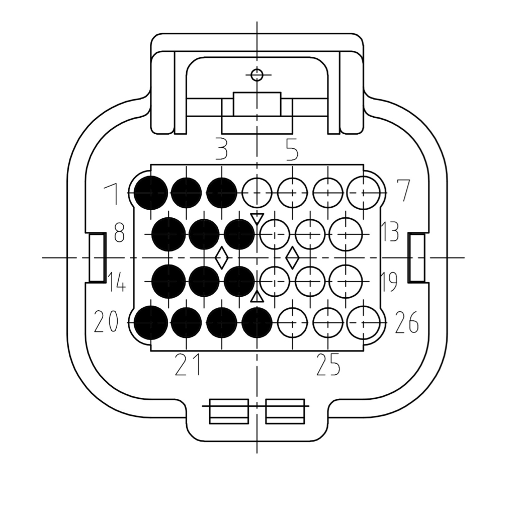
| Signal | Description | Uneven slot | Even slot |
|---|---|---|---|
| SUPPLY 1 | Module supply | 7 | 1 |
| SUPPLY 2 | Module supply | 6 | 2 |
| OUT1 | Signal out 1 | 13 | 8 |
| OUT2 | Signal out 2 | 19 | 14 |
| OUT3 | Signal out 3 | 12 | 9 |
| OUT4 | Signal out 4 | 18 | 15 |
| OUT5 | Signal out 5 | 11 | 10 |
| OUT6 | Signal out 6 | 17 | 16 |
| OUT7 | Signal out 7 | 25 | 21 |
| OUT8 | Signal out 8 | 24 | 22 |
| OUT9 | Signal out 9 | 5 | 3 |
| OUT10 | Signal out 10 | 4 | 23 |
| GROUND | Module ground | 26 | 20 |
Pinout Moduline M1
Four module slots on 34-position connectors. Connector A carries slots 1 and 2, connector B slots 3 and 4. The pin numbers are the same on both. Slots 1 and 3 use the uneven layout, slots 2 and 4 the even one.
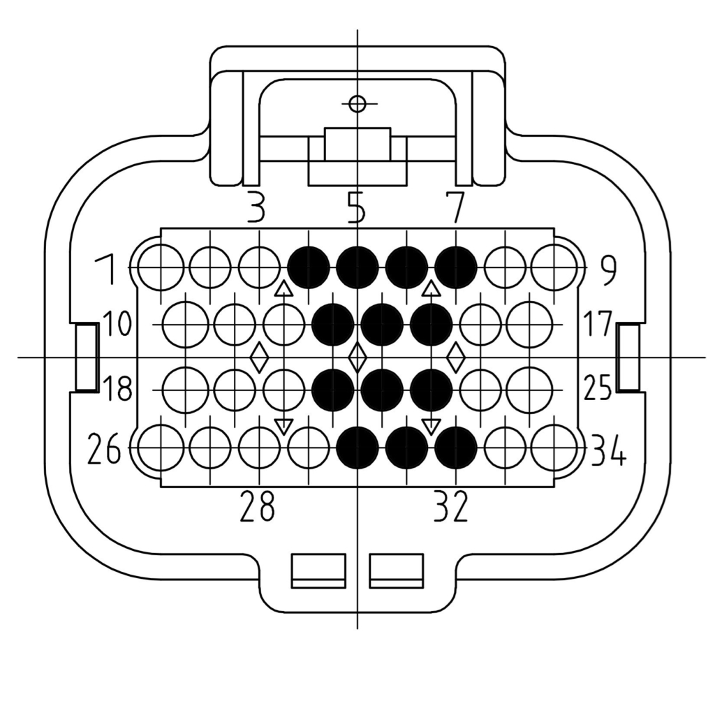
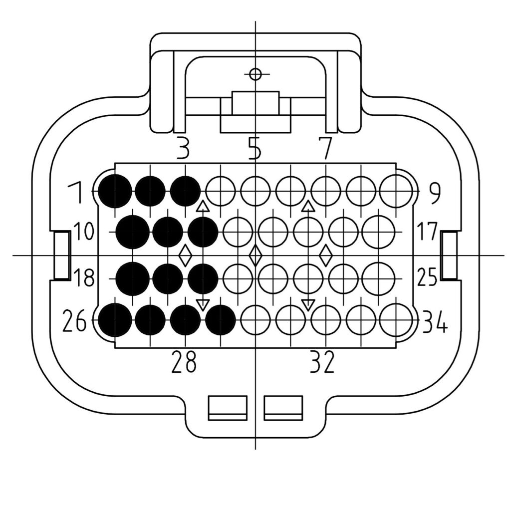
| Signal | Description | Uneven slot | Even slot |
|---|---|---|---|
| SUPPLY 1 | Module supply | 7 | 1 |
| SUPPLY 2 | Module supply | 6 | 2 |
| OUT1 | Signal out 1 | 15 | 10 |
| OUT2 | Signal out 2 | 23 | 18 |
| OUT3 | Signal out 3 | 14 | 11 |
| OUT4 | Signal out 4 | 22 | 19 |
| OUT5 | Signal out 5 | 13 | 12 |
| OUT6 | Signal out 6 | 21 | 20 |
| OUT7 | Signal out 7 | 31 | 27 |
| OUT8 | Signal out 8 | 30 | 28 |
| OUT9 | Signal out 9 | 5 | 3 |
| OUT10 | Signal out 10 | 4 | 29 |
| GROUND | Module ground | 32 | 26 |
Pinout Moduline S1
Two module slots on a single 34-position connector.
| Signal | Description | Slot 1 | Slot 2 |
|---|---|---|---|
| SUPPLY 1 | Module supply | 7 | 1 |
| SUPPLY 2 | Module supply | 6 | 2 |
| OUT1 | Signal out 1 | 15 | 10 |
| OUT2 | Signal out 2 | 23 | 18 |
| OUT3 | Signal out 3 | 14 | 11 |
| OUT4 | Signal out 4 | 22 | 19 |
| OUT5 | Signal out 5 | 13 | 12 |
| OUT6 | Signal out 6 | 21 | 20 |
| OUT7 | Signal out 7 | 31 | 27 |
| OUT8 | Signal out 8 | 30 | 28 |
| OUT9 | Signal out 9 | 5 | 3 |
| OUT10 | Signal out 10 | 4 | 29 |
| GROUND | Module ground | 32 | 26 |
Pinout Moduline HMI1
Two module slots on a single 34-position connector.
| Signal | Description | Slot 1 | Slot 2 |
|---|---|---|---|
| SUPPLY 1 | Module supply | 7 | 1 |
| SUPPLY 2 | Module supply | 6 | 2 |
| OUT1 | Signal out 1 | 15 | 10 |
| OUT2 | Signal out 2 | 23 | 18 |
| OUT3 | Signal out 3 | 14 | 11 |
| OUT4 | Signal out 4 | 22 | 19 |
| OUT5 | Signal out 5 | 13 | 12 |
| OUT6 | Signal out 6 | 21 | 20 |
| OUT7 | Signal out 7 | 31 | 27 |
| OUT8 | Signal out 8 | 30 | 28 |
| OUT9 | Signal out 9 | 5 | 3 |
| OUT10 | Signal out 10 | 4 | 29 |
| GROUND | Module ground | 32 | 26 |
Note: only one application may claim the modules. If a second program initialises the same module – most often a compiled Simulink model next to a Node-RED flow – it causes strange behaviour. Use the CodeBase, Simulink or Node-RED, not two of them at the same time.
Programming with the CodeBase
The GOcontroll CodeBase is the C library for writing your own program. The module is handled through GO_module_output.h and one _outputModule instance. Configure it before you drive it, and initialise the communication before you assign the slot:
static _outputModule outputModule;

GO_board_get_hardware_version();
GO_module_output_set_module_type(&outputModule, OUTPUTMODULE10CHANNEL);
GO_communication_modules_initialize(MODULESLOT1);
GO_module_output_set_module_slot(&outputModule, MODULESLOT1);

for (uint8_t ch = OUTPUTCHANNEL1; ch <= OUTPUTCHANNEL10; ch++) {
    GO_module_output_10ch_configure_channel(&outputModule, ch,
                                            OUTPUTFUNC_10CH_HIGHSIDEDUTY);
}

GO_module_output_configure_frequency(&outputModule,
                                     OUTPUTFREQCHANNEL1AND2,
                                     OUTPUTFREQ_200HZ);

GO_module_output_configuration(&outputModule);
The channel call takes no maximum current, no peak and hold parameters and no fast loop settings: this module does not have those. The frequency call takes a channel pair, OUTPUTFREQCHANNEL1AND2 up to OUTPUTFREQCHANNEL9AND10_10CH, and both calls have to happen before GO_module_output_configuration(), which is the single call that ships the configuration to the module.
Use the OUTPUTFUNC_10CH_ macros. The OUTPUTFUNC_6CH_ macros belong to the 6 Channel Output Module and their numeric values overlap: OUTPUTFUNC_6CH_HALFBRIDGE carries the same number as OUTPUTFUNC_10CH_HIGHSIDEDUTY and OUTPUTFUNC_6CH_LOWSIDEDUTY the same as OUTPUTFUNC_10CH_HIGHSIDEBOOL, so the wrong macro is accepted without an error and the channel runs a function you did not ask for. The same holds for the frequencies: OUTPUTFREQ_6CH_2KHZ and up are rejected on this module.
Be aware that GO_communication_modules_initialize() must be called before GO_module_output_set_module_slot(). The initialize call fills the module occupancy data that set_module_slot uses to verify the module is really present. In the other order you get a contested slot error at runtime.
Driving the module is one call in your application loop, which also brings the feedback back:
outputModule.value[OUTPUTCHANNEL1] = 500;

GO_module_output_send_values(&outputModule);

/* outputModule.temperature, .ground, .supply, .totalCurrent
   and .errorCode now hold what the module sent back */
Keep that call between 10 ms and 400 ms apart: faster than 10 ms overdrives the module, and once 600 ms pass without a message the fail-safe switches the outputs off. The 400 ms ceiling keeps a margin against that threshold; ten milliseconds is the usual loop time. The complete example is in examples/output_module_10ch/ of the CodeBase; it also shows a shutdown callback that switches every channel off before the program exits.
Programming with Simulink
The GOcontroll blockset for MATLAB Simulink holds the block Output Module (10 channel), in the Modules group of the library browser. See using the blockset and create model to get started.
The block has ten uint16 inputs, one per channel, and no outputs. The input labels show the connector pin that belongs to the controller type and slot you selected, so you can trace a channel from the model back to the wiring.
Its mask holds the sample time, the controller type and the module slot, a frequency per channel pair, and the function of each channel. Use a sample time of 100 ms or lower.
The feedback from the module has its own block, Output Module Monitor (10 channel), with five outputs: the module temperature, the ground shift in mV, the supply voltage in mV, the module status and the total module current in mA. The ground shift should stay below 50 mV.
Programming with Node-RED
The GOcontroll nodes are installed on the controller by default. The node for this module is 10 Ch Output Mod, in the GOcontroll section of the palette. See first flow for building a flow.
Note: the Moduline S1 does not run Node-RED.
In the node you set the module slot, the sample time (200 ms, 100 ms or 50 ms), the frequency per channel pair, and per channel its function. Each channel also gets a key: the name you use to address it. Use a descriptive name, it makes the rest of the flow readable.
You drive the outputs by sending a message into the node that carries those keys. The default names are outputSignal1 to outputSignal10:
{"outputSignal1": 500}You may combine as many channels in one message as you like, and a channel you leave out keeps the value it already had. Values run from 0 to 1000; anything outside that range is ignored.
Every sample period the node sends out a message with the feedback from the module:
{"moduleTemperature": 28,
 "moduleGroundShift": 0,
 "moduleVoltage": 14400,
 "moduleCurrent": 5235,
 "moduleStatus": 0}
The Object I/O (legacy shape) checkbox determines where those keys end up. Enabled, they sit directly on the message. Disabled, they sit in msg.payload, which is the Node-RED convention. The same choice applies to the messages you send into the node.
The node shows the article number and the firmware version of the module as its status. If the slot holds a different module type, the status turns red and reports that the selected module does not match the module present in this slot.
Module firmware
The module runs its own firmware, which drives the output stages according to the configuration your application sends and reports the module measurements back. Use go-modules to check the installed version and to update it, and identify to list the modules the controller detects.
Also see
- 6 Channel Output Module – fewer channels, high and low side switching, peak and hold, and a current measurement per channel
- Important notice – the sample time to use with output based modules
- Hot plugging – why connectors are never connected or disconnected under power
- go-modules – reading out and updating module firmware
- 10 Channel Output Module product page – specifications and ordering