
Moduline L4
The GOcontroll Moduline L4 is a modular programmable controller offering up to 8 IO modules and various communication interfaces.

The controller runs Linux on an NXP i.MX8M Mini application processor and takes up to eight plug-in modules, so the modules you fit determine what it can measure and control. Five 26-position automotive connectors carry those module slots together with the supply, the four CAN interfaces and the LIN interface. For the complete specifications and for ordering see the product page.
On this page
- At a glance
- Module slots
- Power supply
- Communication interfaces
- Connections and pinout
- Configurations
- 3D model
At a glance
These are the specifications of the controller itself, without modules.
- Module slots – 8, for Moduline compatible modules
- Processor – i.MX8M Mini, quad ARM Cortex-A53, 1.6 GHz for each core
- Memory – 1 GB RAM, 4 GB eMMC flash
- Operating system – Linux
- Boot time – 2.4 to 2.6 seconds for a compiled Simulink model, 8 to 10 seconds for the Node-RED service
- Built-in LEDs – 4 programmable high brightness multicolour RGB
- Enclosure – CNC machined billet aluminium EN AW-5083, anodised grey, IP67
- Temperature range – from -20 °C to 85 °C
- Weight – 1380 gram without modules
Module slots
The Moduline L4 has eight module slots, and every Moduline module fits every slot. The modules you fit determine what the controller can measure and control.
The slots sit on four of the five automotive connectors, two slots on each. Slots 1, 3, 5 and 7 use the uneven pin layout of their connector and slots 2, 4, 6 and 8 the even one, so a module occupies thirteen of the twenty-six pins. The five connectors provide up to 80 I/O in total.
Which pin carries which signal depends on the module. Every module page lists its own pinout for each controller and slot: 6 Channel Input Module, 10 Channel Input Module, 4-20 mA Input Module, Loadcell Module, 6 Channel Output Module, 10 Channel Output Module, 2 Channel Power Bridge Module and Multibus Module.
Output modules are supplied separately from the controller, so an output module can run on a different working voltage than the controller itself.
Power supply
The controller is powered over connector C. Terminal K30 on pins 5, 6 and 7 is the battery positive connection and terminal K31 on pins 24, 25 and 26 is the battery negative connection. The three K15 contact inputs on pins 2, 3 and 4 switch the controller on.
An enable input boots the controller when it is high. When the application detects that an enable input has gone low, it can finish its routines before the controller shuts down. The enable pins only activate the controller; the supply itself comes from K30.
- Supply voltage (K30) – 8 – 32 VDC
- Contact voltage (K15, all K15 pins) – 8 – 32 VDC
- Nominal current consumption when active, no modules installed – 310 mA at 12 VDC, 200 mA at 24 VDC
- Current consumption when switched off, K15 low – less than 1 mA
- Load dump protection – designed according to ISO7637-2 5a/5b
The current figures above are for the controller without modules installed. The voltage limits that apply to every Moduline controller are covered under Supply voltage.
Communication interfaces
The controller has four CAN 2.0 B interfaces and one LIN interface, all five on connector C. The LIN interface works in a master or in a slave configuration; pin 9 of connector C is the LIN supply line for master operation.
Ethernet is 10/100 Mbps and USB is 2.0. The USB connection runs over an M12 connector and needs a dedicated M12 to USB cable – see USB. RS232 is available as an assembly option.
The controller has two M12 connectors: one carries Ethernet, the other USB and RS232.
Wireless communication and positioning are optional and are not fitted on every controller. They use external antennas on the three SMA connectors: one for Wi-Fi and Bluetooth, one for LTE/GSM/GPRS and one for GNSS.
- Bluetooth – 5.1 BR/EDR/LE, 3MPHY
- WiFi – Wi-Fi 4, 802.11 b/g/n
- Cellular communication – LTE CAT-4 (LTE-TDD/LTE-FDD/HSPA+/GSM/GPRS/EDGE)
- Positioning GNSS – GPS/GLONASS/BeiDou/Galileo
Connections and pinout
The controller has five 26-position automotive connectors, lettered A to E, plus two M12 connectors and three SMA connectors. Connector C is the middle one of the five and carries the controller itself: the supply, the three enable inputs, the reset input, the four CAN interfaces and the LIN interface. Connectors A, B, D and E carry the eight module slots, two slots on each, and no controller signals.
The M12 and SMA connectors are not part of the pinout below; they are described under Communication interfaces.

The table below gives every pin of connector C. Connectors A, B, D and E have the same 26-position numbering and each of them is divided between its two module slots; their pin ranges are listed per connector below.
On the Moduline L4 the supply has a connector of its own: K30 on pins 5, 6 and 7 of connector C, K31 on pins 24, 25 and 26, and the three K15 contact inputs on pins 2, 3 and 4.
Connectors may never be hot-plugged: remove power before you remove or install a connector.
Connector C – the system connector
Pin 23 is not connected; the other twenty-five pins all carry a controller signal.
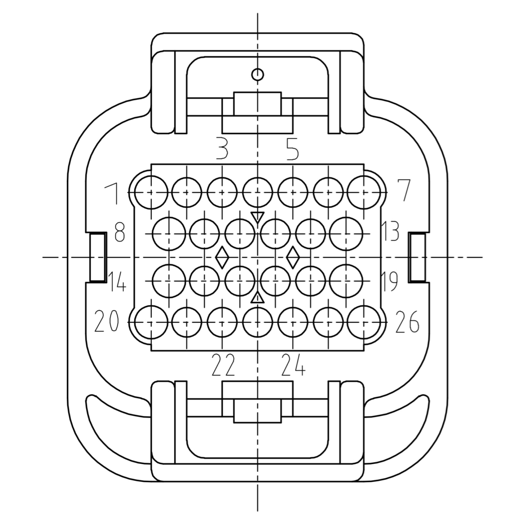
| Pin | Signal | Description |
|---|---|---|
| 1 | Controller reset | Reset controller (active high) |
| 2 | K15 (contact) | Switch on controller 1 (active high) |
| 3 | K15 (contact) | Switch on controller 2 (active high) |
| 4 | K15 (contact) | Switch on controller 3 (active high) |
| 5 | K30 (supply) | Battery positive connection |
| 6 | K30 (supply) | Battery positive connection |
| 7 | K30 (supply) | Battery positive connection |
| 8 | LIN bus | LIN communication line |
| 9 | LIN supply | LIN supply line (master) |
| 10 | LIN ground | Optional reference ground |
| 11 | CAN 4 ground | Optional ground for shielding |
| 12 | CAN 4 high | CAN high line |
| 13 | CAN 4 low | CAN low line |
| 14 | CAN 1 low | CAN low line |
| 15 | CAN 1 high | CAN high line |
| 16 | CAN 1 ground | Optional ground for shielding |
| 17 | CAN 3 ground | Optional ground for shielding |
| 18 | CAN 3 high | CAN high line |
| 19 | CAN 3 low | CAN low line |
| 20 | CAN 2 low | CAN low line |
| 21 | CAN 2 high | CAN high line |
| 22 | CAN 2 ground | Optional ground for shielding |
| 23 | NC | Not connected |
| 24 | K31 (ground) | Battery negative connection |
| 25 | K31 (ground) | Battery negative connection |
| 26 | K31 (ground) | Battery negative connection |
Connector A – module slots 1 and 2
Connector A carries module slot 1 on the uneven pins and module slot 2 on the even pins.
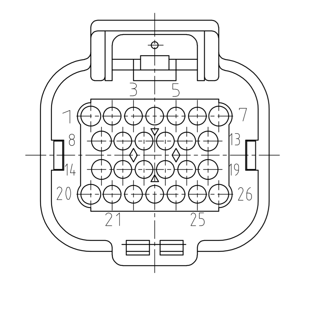
Pins 4-7, 11-13, 17-19 and 24-26 belong to module slot 1; pins 1-3, 8-10, 14-16 and 20-23 to module slot 2. Which signal each pin carries depends on the module fitted. Each module lists its pinout in its own knowledge base article.
Connector B – module slots 3 and 4
Connector B carries module slot 3 on the uneven pins and module slot 4 on the even pins.
Pins 4-7, 11-13, 17-19 and 24-26 belong to module slot 3; pins 1-3, 8-10, 14-16 and 20-23 to module slot 4. Which signal each pin carries depends on the module fitted. Each module lists its pinout in its own knowledge base article.
Connector D – module slots 5 and 6
Connector D carries module slot 5 on the uneven pins and module slot 6 on the even pins.
Pins 4-7, 11-13, 17-19 and 24-26 belong to module slot 5; pins 1-3, 8-10, 14-16 and 20-23 to module slot 6. Which signal each pin carries depends on the module fitted. Each module lists its pinout in its own knowledge base article.
Connector E – module slots 7 and 8
Connector E carries module slot 7 on the uneven pins and module slot 8 on the even pins.
Pins 4-7, 11-13, 17-19 and 24-26 belong to module slot 7; pins 1-3, 8-10, 14-16 and 20-23 to module slot 8. Which signal each pin carries depends on the module fitted. Each module lists its pinout in its own knowledge base article.
Configurations
Which modules and which options a particular Moduline L4 contains is set by its part number, and the configuration document of every published part number is listed under Moduline L4 configurations.
3D model
The 3D model of the Moduline L4 is available as a STEP file in a ZIP archive. Use it to check the fit and the mounting of the controller, and to place it in your own CAD assembly.
Also see
- Supply voltage – the supply limits of the Moduline controllers
- Hot plugging – why connectors are never connected or disconnected under power
- identify – reading the controller and its modules from the running controller
- go-modules – reading out and updating module firmware
- Moduline L4 product page – specifications and ordering