
6 Channel Input Module
The 6 Channel Input Module is a GOcontroll Moduline compatible expansion card that adds six general-purpose input channels to your Moduline controller.
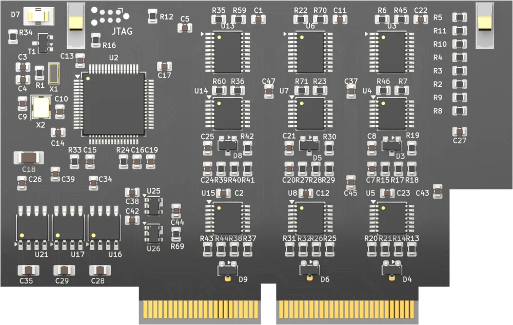
Each channel is configured on its own as an analog, digital, frequency, duty cycle, rotation speed or pulse counter input. The module fits every module slot of a Moduline L4, Moduline M1, Moduline S1 or Moduline HMI1. The article number is 201001 followed by two digits for the hardware version. For the electrical specifications see the product page.
On this page
- Channels and configuration
- Connections and pinout
- Programming with the CodeBase
- Programming with Simulink
- Programming with Node-RED
- Module firmware
Channels and configuration
You set the function of each channel. The function determines what the module measures and what value it returns:
- Analog input – decimal: the voltage as a raw 12 bit value, 0 to 4095 over the selected reading range.
- Analog input – mV: the voltage in millivolt. On the 0 – 12 V range, 8.54 V is returned as 8540.
- Digital input – status: the state of the pin, high or low.
- Digital input – frequency: the frequency of the signal, with a resolution of 1 Hz.
- Digital input – duty cycle low time: the percentage of the period the signal is low, in steps of 0.1%. A signal that is 65% active high returns 350.
- Digital input – duty cycle high time: the same for the high time. That signal returns 650.
- Digital input – rotation speed: the speed calculated from the pulse train, using the pulses per rotation you set.
- Digital input – pulse counter: a running count of the pulses. Channels count in pairs, 1 with 2, 3 with 4 and 5 with 6. The counter starts at 0 and can be set to another value from your application.
Three settings apply on top of the function. The reading range is 0 – 5 V, 0 – 12 V or 0 – 24 V and works as a divider in front of the converter, so pick the range that fits your sensor: a sensor that delivers 0 to 10 V reads best on the 0 – 12 V range. A pull-up or pull-down resistor of 3.2, 4.7 or 10 kOhm can be switched in for sensors that do not drive both signal levels themselves, such as a switch to ground. The analog filter averages up to 1000 samples and applies to the two analog functions only.
The module also carries three 5 V sensor supply outputs to power your sensors. They are independent and each one is switched on or off in your configuration, so enable only the supplies you have wired. Their current rating counts per supply pin, not for the three together. Each supply drives one pin; the pinout below shows which pin belongs to which supply.
Connections and pinout
The module presents three 5 V sensor supply pins, the six input signals IN1 to IN6, three sensor ground pins and one pin without a function. Which connector pin carries which signal depends on the controller and on the slot.
If more supply or ground connections are needed than the module has pins, the wires can be spliced.
Pinout Moduline L4
Eight module slots on 26-position connectors. Connector A carries slots 1 and 2, connector B slots 3 and 4, connector D slots 5 and 6, and connector E slots 7 and 8. The pin numbers are the same on all four. Slots 1, 3, 5 and 7 use the uneven layout, slots 2, 4, 6 and 8 the even one.
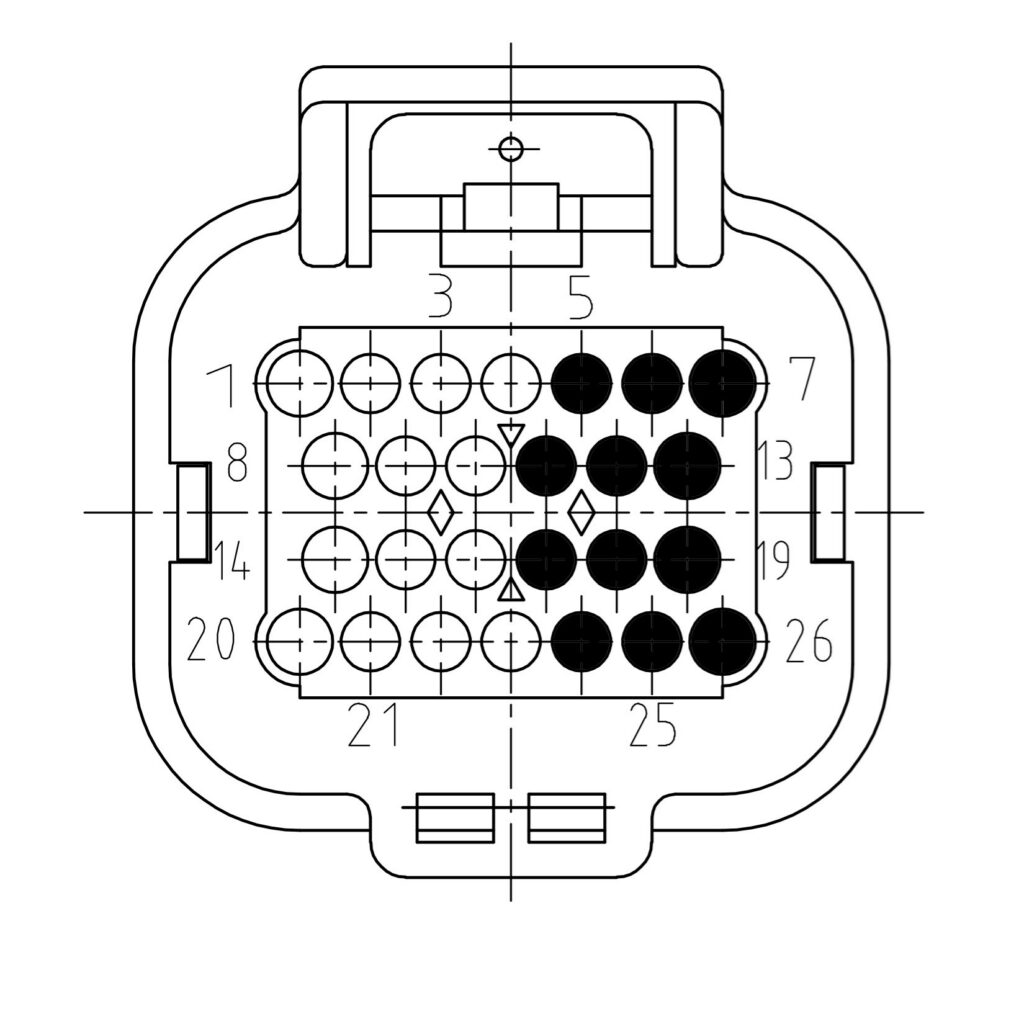
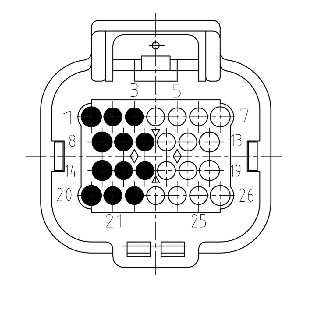
| Signal | Description | Uneven slot | Even slot |
|---|---|---|---|
| SUPPLY 1 | 5V sensor supply 1 | 7 | 1 |
| SUPPLY 2 | 5V sensor supply 2 | 6 | 2 |
| SUPPLY 3 | 5V sensor supply 3 | 5 | 3 |
| IN1 | Signal in 1 | 13 | 8 |
| IN2 | Signal in 2 | 19 | 14 |
| IN3 | Signal in 3 | 12 | 9 |
| IN4 | Signal in 4 | 18 | 15 |
| IN5 | Signal in 5 | 11 | 10 |
| IN6 | Signal in 6 | 17 | 16 |
| GROUND | Sensor ground | 26 | 20 |
| GROUND | Sensor ground | 25 | 21 |
| GROUND | Sensor ground | 24 | 22 |
| NC | No functionality | 4 | 23 |
Pinout Moduline M1
Four module slots on 34-position connectors. Connector A carries slots 1 and 2, connector B slots 3 and 4. The pin numbers are the same on both. Slots 1 and 3 use the uneven layout, slots 2 and 4 the even one.
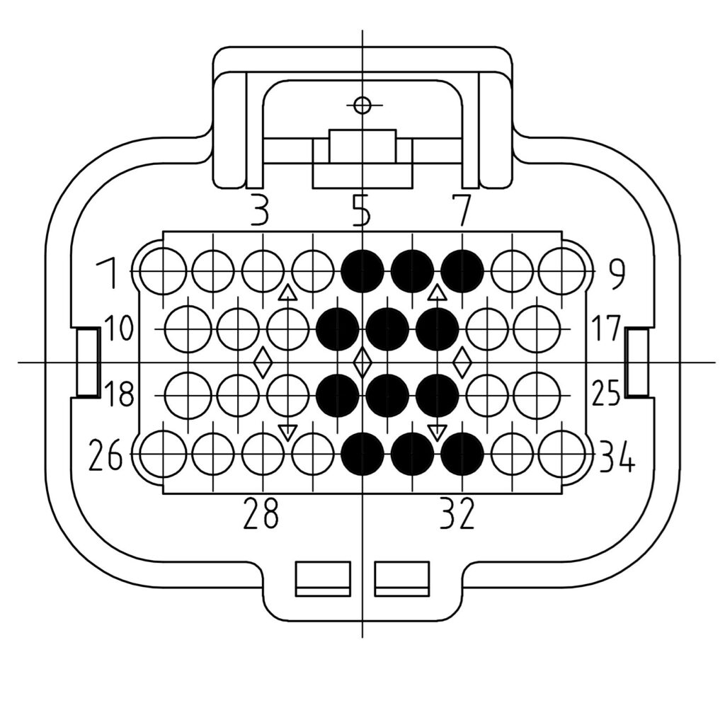
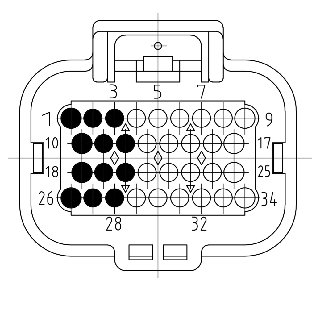
| Signal | Description | Uneven slot | Even slot |
|---|---|---|---|
| SUPPLY 1 | 5V sensor supply 1 | 7 | 1 |
| SUPPLY 2 | 5V sensor supply 2 | 6 | 2 |
| SUPPLY 3 | 5V sensor supply 3 | 5 | 3 |
| IN1 | Signal in 1 | 15 | 10 |
| IN2 | Signal in 2 | 23 | 18 |
| IN3 | Signal in 3 | 14 | 11 |
| IN4 | Signal in 4 | 22 | 19 |
| IN5 | Signal in 5 | 13 | 12 |
| IN6 | Signal in 6 | 21 | 20 |
| GROUND | Sensor ground | 32 | 26 |
| GROUND | Sensor ground | 31 | 27 |
| GROUND | Sensor ground | 30 | 28 |
| NC | No functionality | 4 | 29 |
Pinout Moduline S1
Two module slots on a single 34-position connector.
| Signal | Description | Slot 1 | Slot 2 |
|---|---|---|---|
| SUPPLY 1 | 5V sensor supply 1 | 7 | 1 |
| SUPPLY 2 | 5V sensor supply 2 | 6 | 2 |
| SUPPLY 3 | 5V sensor supply 3 | 5 | 3 |
| IN1 | Signal in 1 | 15 | 10 |
| IN2 | Signal in 2 | 23 | 18 |
| IN3 | Signal in 3 | 14 | 11 |
| IN4 | Signal in 4 | 22 | 19 |
| IN5 | Signal in 5 | 13 | 12 |
| IN6 | Signal in 6 | 21 | 20 |
| GROUND | Sensor ground | 32 | 26 |
| GROUND | Sensor ground | 31 | 27 |
| GROUND | Sensor ground | 30 | 28 |
| NC | No functionality | 4 | 29 |
Pinout Moduline HMI1
Two module slots on a single 34-position connector.
| Signal | Description | Slot 1 | Slot 2 |
|---|---|---|---|
| SUPPLY 1 | 5V sensor supply 1 | 7 | 1 |
| SUPPLY 2 | 5V sensor supply 2 | 6 | 2 |
| SUPPLY 3 | 5V sensor supply 3 | 5 | 3 |
| IN1 | Signal in 1 | 15 | 10 |
| IN2 | Signal in 2 | 23 | 18 |
| IN3 | Signal in 3 | 14 | 11 |
| IN4 | Signal in 4 | 22 | 19 |
| IN5 | Signal in 5 | 13 | 12 |
| IN6 | Signal in 6 | 21 | 20 |
| GROUND | Sensor ground | 32 | 26 |
| GROUND | Sensor ground | 31 | 27 |
| GROUND | Sensor ground | 30 | 28 |
| NC | No functionality | 4 | 29 |
Note: only one application may claim the modules. If a second program initialises the same module – most often a compiled Simulink model next to a Node-RED flow – it causes strange behaviour. Use the CodeBase, Simulink or Node-RED, not two of them at the same time.
Programming with the CodeBase
The GOcontroll CodeBase is the C library for writing your own program. The module is handled through GO_module_input.h and one _inputModule instance. Configure it before you read it, and initialise the communication before you assign the slot:
static _inputModule inputModule;

GO_board_get_hardware_version();
GO_module_input_set_module_type(&inputModule, INPUTMODULE6CHANNEL);
GO_communication_modules_initialize(MODULESLOT1);
GO_module_input_set_module_slot(&inputModule, MODULESLOT1);

GO_module_input_6ch_configure_supply(&inputModule,
                                     INPUTSENSSUPPLYON,
                                     INPUTSENSSUPPLYOFF,
                                     INPUTSENSSUPPLYOFF);

for (uint8_t ch = INPUTCHANNEL1; ch <= INPUTCHANNEL6; ch++) {
    GO_module_input_6ch_configure_channel(&inputModule, ch,
                                          INPUTFUNC_MVANALOG,
                                          INPUTVOLTAGERANGE_24V,
                                          INPUTPULLUP6CH_10K,
                                          INPUTPULLDOWN6CH_3_3K,
                                          0,
                                          10);
}

GO_module_input_configuration(&inputModule);
The last two parameters are the pulses per rotation and the analog filter samples. Use the INPUTPULLUP6CH_ and INPUTPULLDOWN6CH_ macros: the 10CH_ macros belong to the 10 channel input module and their values do not match.
Be aware that GO_communication_modules_initialize() must be called before GO_module_input_set_module_slot(). The initialize call fills the module occupancy data that set_module_slot uses to verify the module is really present. In the other order you get a contested slot error at runtime.
Reading the module is one call in your application loop:
GO_module_input_receive_values(&inputModule);

/* inputModule.value[0] .. inputModule.value[5] hold channel 1 .. 6 */
A pulse counter is set with GO_module_input_reset_puls_counter(). The complete example is in examples/input_module_6ch/ of the CodeBase.
Programming with Simulink
The GOcontroll blockset for MATLAB Simulink holds the block Input Module (6 channel), in the Modules group of the library browser. See using the blockset and create model to get started.
The block has no inputs and six int32 outputs, one per channel. The output labels show the connector pin that belongs to the controller type and slot you selected, so you can trace a signal from the model back to the wiring.
Its mask holds the sample time, the controller type and the module slot, a switch for each of the three sensor supplies, and per channel the function, the reading range, the analog filter samples, the pulses per rotation and the pull-up and pull-down resistor.
To set a pulse counter to a new value, add the Reset Pulse Counter (6 channel) block from the same group. You select the controller type, the module slot and the channel in its mask, and you feed it a trigger and the value to write. A change on the trigger sends the value to the module.
Programming with Node-RED
The GOcontroll nodes are installed on the controller by default. The node for this module is 6 Ch Input Mod, in the GOcontroll section of the palette. See first flow for building a flow.
Note: the Moduline S1 does not run Node-RED.
In the node you set the module slot, the sample time (1 s, 200 ms, 100 ms or 50 ms), the three sensor supplies, and per channel the signal type, the reading range and the pull-up and pull-down resistor. Each channel also gets a signal key: the name it carries in the output message. Use a descriptive name, it makes the rest of the flow readable.
The node sends one message per sample, holding the six keys and their values:
{"throttlePosition": 2766,
 "engineSpeed": 2650,
 "engineOilPressure": 2456,
 "engineTemperature": 62,
 "oilTemperature": 92,
 "ConnectorApin13": 1002}
The Object I/O (legacy shape) checkbox determines where those keys end up. Enabled, they sit directly on the message. Disabled, they sit in msg.payload, which is the Node-RED convention. The same choice applies to messages you send into the node.
A pulse counter is set by sending a message into the node. The counters are shared per channel pair:
{"channel12pulses": 0}The other keys are channel34pulses and channel56pulses, and you may combine them in one message. The value must fit in a signed 32 bit integer.
The node shows the article number and the firmware version of the module as its status. If the slot holds a different module type, the status turns red and reports that the selected module does not match the module present in this slot.
Module firmware
The module runs its own firmware, which converts the signal according to the configuration your application sends. Use go-modules to check the installed version and to update it, and identify to list the modules the controller detects.
Keep the module on a recent version. Firmware 2.0.0 introduced a new communication protocol between the controller and the module, and the controller selects the matching protocol from the version it reads out.
Also see
- Hot plugging – removing and inserting a module
- go-modules – reading out and updating module firmware
- 6 Channel Input Module product page – specifications and ordering